
PPK-Q030 Digital Pressure Sensor: I²C and UART Guide #
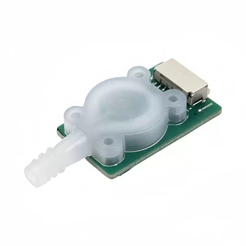
The PPK-Q030 is a digital air pressure sensor module with a 0–1500 kPa absolute-pressure range. This guide explains how to choose an interface and interpret readings in a microcontroller project. I²C and UART are separate purchase options; choose the version that matches your controller and software.
1. Choose the right output version #
| Configuration | Controller interface | Communication method | Choose it when |
|---|---|---|---|
| PPK-Q030 — I²C | SCL and SDA bus signals | Register-based commands and reads; clock up to 400 kHz | Your controller software uses an I²C bus. |
| PPK-Q030 — UART | UART transmit and receive signals | 9600 baud, 8 data bits, no parity, 1 stop bit | Your controller software uses a serial port. |
These interface names describe communication signals, not the positions or colors of the module cable wires. They do not mean that both interfaces are available on every purchased module.
2. Understand absolute pressure #
Absolute pressure is referenced to a vacuum. Gauge pressure is relative to the surrounding atmosphere. A sensor exposed to ambient air therefore does not normally read zero absolute pressure.
For a project that needs gauge pressure, subtract a suitable ambient absolute-pressure reference from the measured absolute pressure. Do not subtract a fixed atmospheric value unless that approximation is appropriate for the project: ambient pressure changes with location and conditions.
3. Check size and supply requirements #
| Parameter | Value |
|---|---|
| Measured medium | Air |
| Pressure range | 0–1500 kPa absolute |
| Operating supply | 2.4–5.5 V |
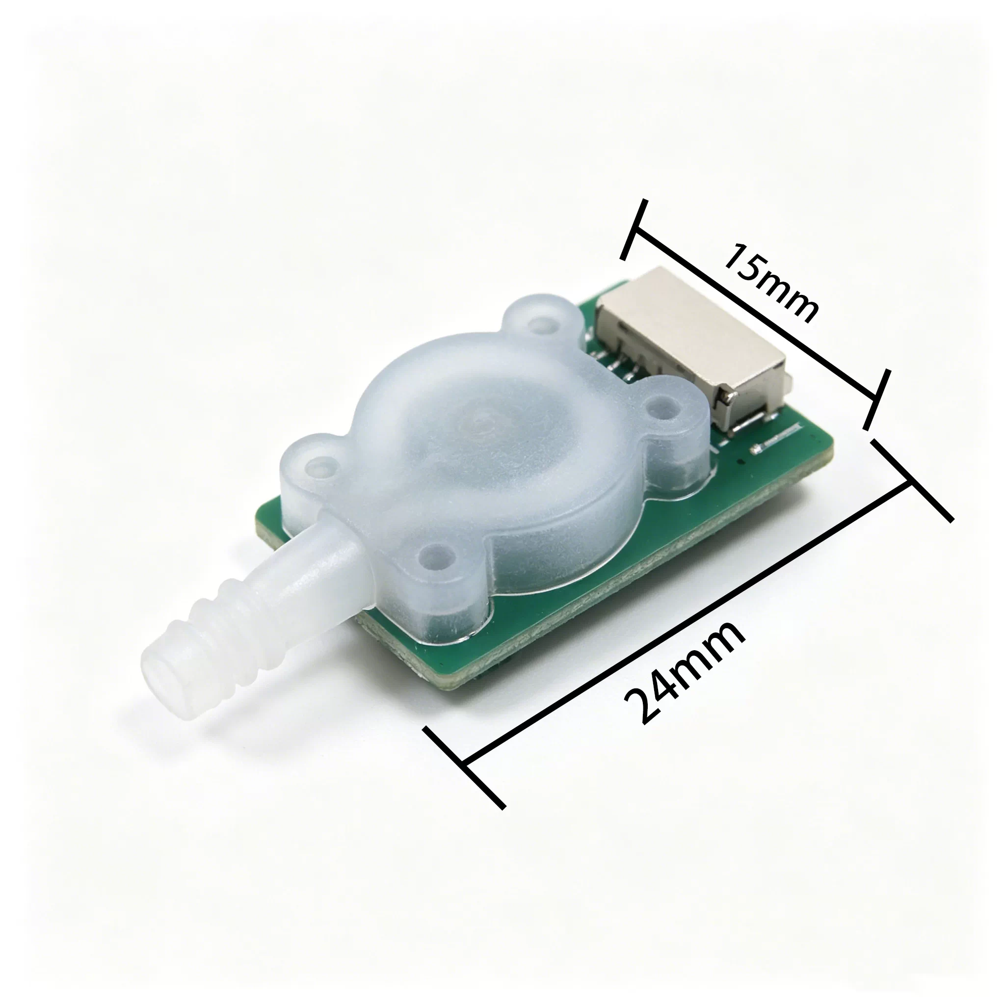
| Module footprint | 24 × 15 mm |
| Conversion current | 1.5 mA typical |
| Standby current | 2 µA typical; 3.5 µA maximum |
Use 1500 kPa as the measurement-range limit. Do not treat an absolute-maximum or overpressure rating as an extended measurement range. This guide does not establish a whole-module waterproof rating or suitability for liquid contact.
4. Use the temperature-first measurement sequence #
The documented I²C and UART procedures require temperature acquisition before pressure conversion. The internal compensation uses the current temperature.
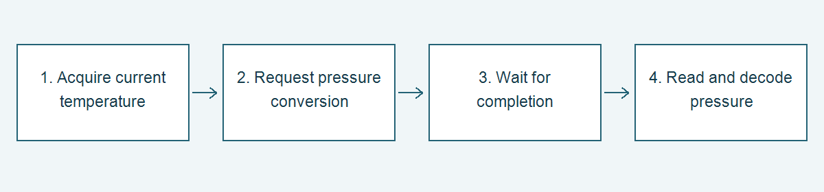
- Acquire the current temperature using the selected interface.
- Request the pressure conversion.
- Wait for the documented completion indication or response.
- Read and decode the returned pressure value.
5. I²C command and read sequence #
The documented address bytes are 0xDA for writing and 0xDB for reading. For controller libraries that expect a seven-bit device address, use 0x6D; the library supplies the read/write bit. Check the convention of your library before passing an address.
| Operation | Register | Command or data |
|---|---|---|
| Request temperature conversion | 0x0A | Write 0x04 |
| Request pressure conversion | 0x0A | Write 0x06 |
| Check conversion completion | 0x13 | Bit 0 indicates completion when set |
| Read temperature | 0x0F–0x10 | High byte followed by low byte |
| Read pressure | 0x0B–0x0E | Most significant byte first |
Poll for completion rather than guessing a fixed conversion delay. In controller software, include a timeout so an absent or disconnected sensor cannot leave the program waiting indefinitely.
Temperature example:
0x0F = 0x01, 0x10 = 0x02
Raw value = 0x0102 = 258
Temperature = 258 / 10 = 25.8 °C

Pressure example:
0x0B = 0x00, 0x0C = 0x01, 0x0D = 0x86, 0x0E = 0xA0
Raw value = 0x000186A0 = 100000
Pressure = 100000 / 1000 = 100 kPa absolute
These are documented decoding examples, not readings guaranteed for a particular environment.
6. UART communication #
Configure the host serial port for 9600 baud, 8-N-1. The command frame begins with 0x55; a response begins with 0xAA. The documented frame also contains length, command or data-type fields, payload and a checksum. Validate the complete frame before using its payload.
| Command | Purpose |
|---|---|
| 0x0E | Acquire current temperature |
| 0x27 | Acquire high-accuracy temperature |
| 0x0D | Acquire current pressure |
| 0x26 | Acquire high-accuracy pressure |
| 0x3C | Acquire predicted pressure |
The source provides these current-temperature and current-pressure request examples:
Current temperature request: 55 04 0E 6A
Current pressure request:    55 04 0D 88
Request temperature first. The documented response data types include signed 16-bit temperature and unsigned 32-bit pressure. The examples scale temperature by 10 and pressure by 1000 to obtain °C and kPa respectively. Do not assume the I²C byte order applies to the UART payload: the UART example transmits the least significant byte first.
For example, the UART pressure payload A0 86 01 00 represents 0x000186A0, or 100000, yielding 100 kPa. A temperature payload 02 01 represents 258, yielding 25.8 °C. Use signed decoding for negative temperatures.
7. Check the first readings #
- Confirm that software is configured for the purchased interface.
- Confirm the supply and connector assignments before troubleshooting software.
- For an I²C address failure, check whether the library expects 0x6D or explicit address bytes.
- For UART, check 9600 baud and 8-N-1, then validate framing and checksum.
- For a factor-of-1000 pressure error, check the documented raw-value scaling.
- For an apparent offset in open air, check whether the application expects absolute or gauge pressure.
- Repeat temperature acquisition before pressure conversion.
A 24-bit ADC describes the conversion architecture. It must not be interpreted as a guaranteed 24-bit measurement accuracy. Resolution, accuracy and operating conditions are separate specifications.


