
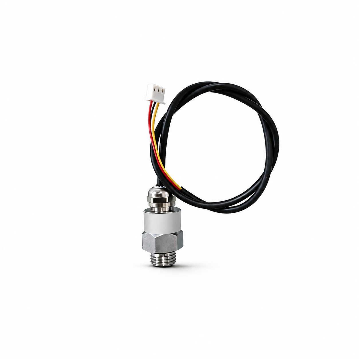
One product family, seven electrical versions #
The PPK-MP28 is offered with voltage, current, and digital outputs. These are separate purchase configurations. A sensor ordered with a voltage output does not become an RS485 sensor through a software setting.
Before choosing a letter code, check the input on the device that will receive the measurement. An analog voltage input, a current input, and a serial interface require different electrical connections. The sensor’s supply voltage is a separate requirement from its output signal.
| Version | Supply | Output | What to match |
|---|---|---|---|
| A | 3.3 V | 0.5–2.5 V | An analog input that accepts the full 0.5–2.5 V signal. |
| B | 5 V | 0.5–4.5 V | An analog input that accepts the full 0.5–4.5 V signal. |
| C | 3.3 V | I²C | An I²C interface, with the device address and data format established before integration. |
| D | 12–24 V | 0–10 V | A voltage input designed for a 0–10 V measurement signal. |
| E | 12–24 V | 4–20 mA | A compatible current input and the correct connection arrangement. |
| F | 12–24 V | RS485 | An RS485 interface and the correct communication protocol. |
| G | 3.3–5 V | UART | A compatible UART interface, including signal levels and serial settings. |
For example, a controller powered from 3.3 V is not automatically compatible with version B: B needs a 5 V supply and can output 4.5 V. Likewise, a 24 V control system does not tell you whether to order D, E, or F. That choice depends on whether its receiving input is 0–10 V, 4–20 mA, or RS485.
For the digital versions, the interface name is only the starting point. RS485 does not by itself mean Modbus. I²C and UART also need device-specific communication information. Establish the protocol, register or message format, and relevant settings before planning the software.
Choose both ends of the pressure range #
The second selector is the measurement range. There are ten options: five beginning at zero and five beginning at −100 kPa. Read the lower limit as carefully as the upper limit, particularly when the measurement needs to include negative pressure.
| Upper limit | Zero-based option | Negative-pressure option |
|---|---|---|
| 100 kPa | 0 to 100 kPa | −100 to 100 kPa |
| 1 MPa | 0 to 1 MPa | −100 kPa to 1 MPa |
| 1.6 MPa | 0 to 1.6 MPa | −100 kPa to 1.6 MPa |
| 3 MPa | 0 to 3 MPa | −100 kPa to 3 MPa |
| 3.5 MPa | 0 to 3.5 MPa | −100 kPa to 3.5 MPa |
The mixed units matter. “−100 kPa to 1 MPa” has a lower limit of −0.1 MPa, not −100 MPa. Choosing the same upper limit does not make the zero-based and negative-pressure versions interchangeable.
Consider a measurement that needs to cover −50 kPa to +80 kPa. The −100 to +100 kPa option includes both ends; the 0 to 100 kPa option does not. This is a range-selection example, not an approval for a particular fluid or installation.
What ±0.5%FS tells you #
The specified accuracy is ±0.5%FS. FS means full scale; it is not a promise of ±0.5% of every reading. Choose a range that covers the expected measurement conditions rather than automatically picking the highest upper limit.
The operating temperature is −40 to 125°C. Keep the temperature rating separate from the pressure range and the electrical supply: meeting one requirement does not establish that the complete installation meets all three.
Check the mechanical fit before the wiring #
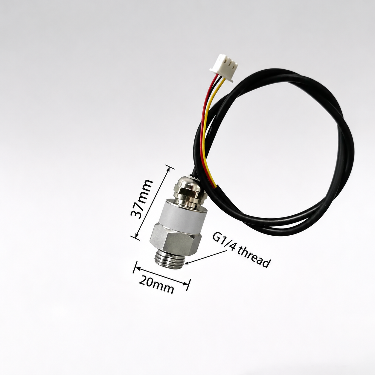
The threaded process connection is G1/4. Match it to the mating fitting and the required sealing arrangement; do not choose a fitting by visual similarity alone. The illustrated body dimensions help with space planning, but leave room for the cable and connector as well.
The medium in contact with the sensor also matters. Establish material and seal compatibility for the actual fluid or gas before installation. A threaded metal body, by itself, does not establish suitability for corrosive media, food contact, or hazardous locations.
Before connecting your selected version #
- Check the exact supply. Do not apply 12–24 V to a 3.3 V or 5 V version.
- Check the receiving input. It must accept the selected output signal or digital interface.
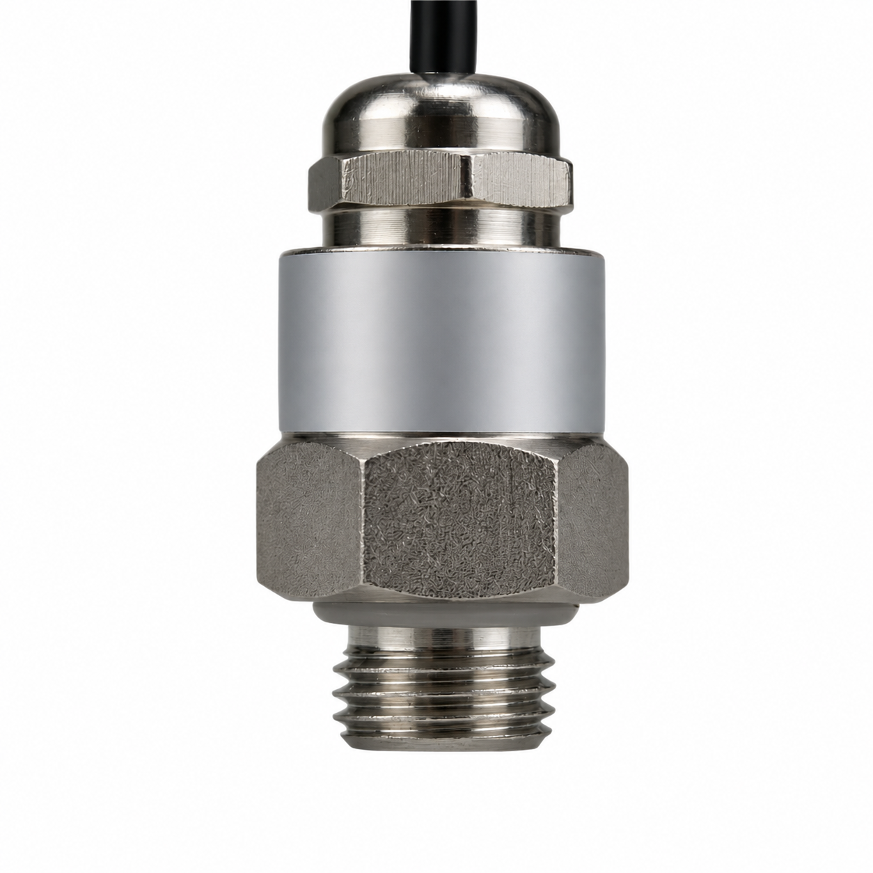
- Use the correct pin assignments. Do not copy wire colors from a photograph of another version.
- Check the pressure limits. Confirm both ends of the selected range and the system’s expected operating conditions.
- Check the process connection and medium. Thread fit and material compatibility are separate checks.
How to place the right order #
Write down the required supply, output, and pressure limits before opening the selectors. For an input accepting 0.5–2.5 V with a 3.3 V sensor supply, start with version A. If that measurement must include negative pressure up to a positive limit of 100 kPa, select −100 to 100 kPa as the range. Other controller requirements lead to a different electrical version, even when the mechanical body looks similar.
View the PPK-MP28 pressure sensor and choose an electrical version and pressure range.


