
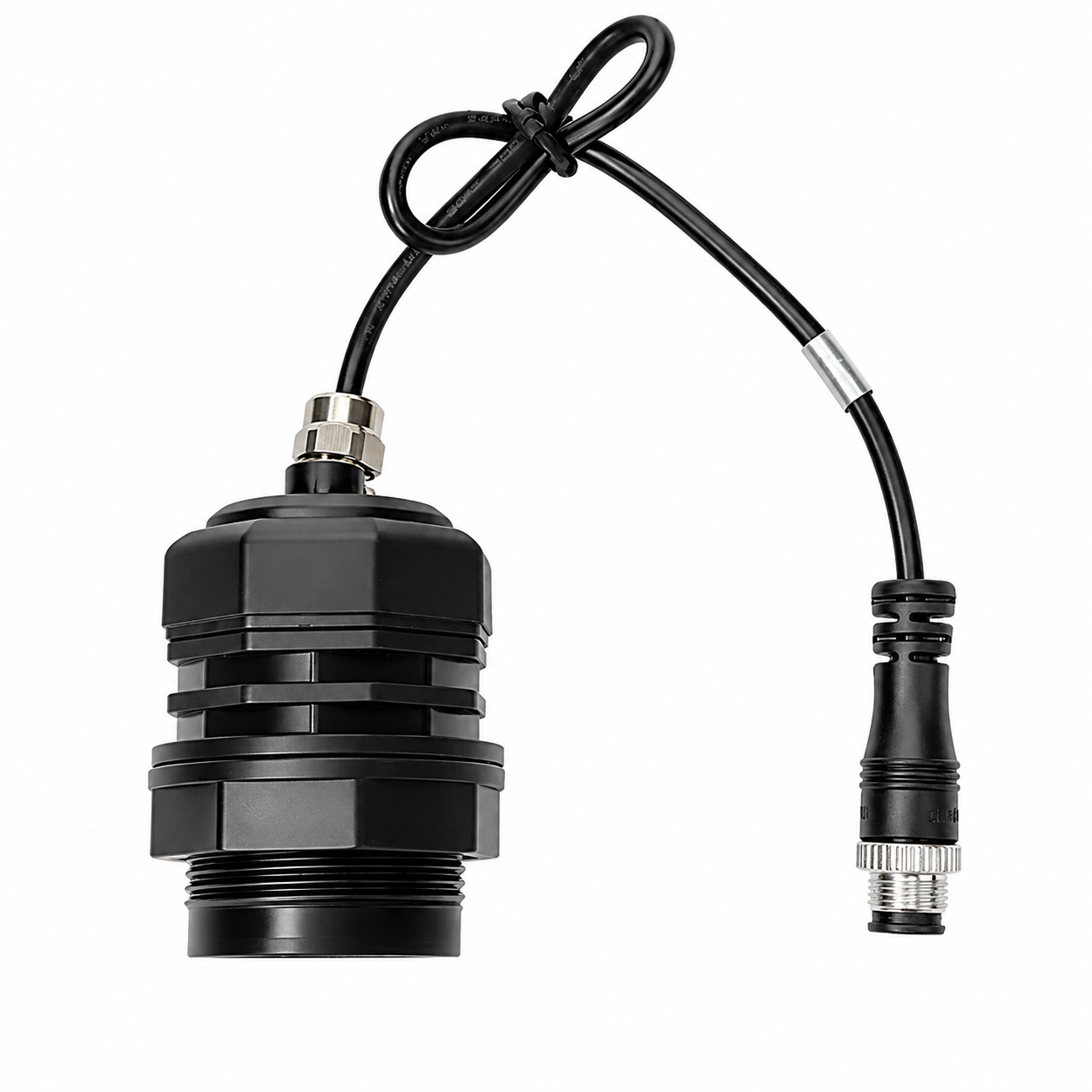
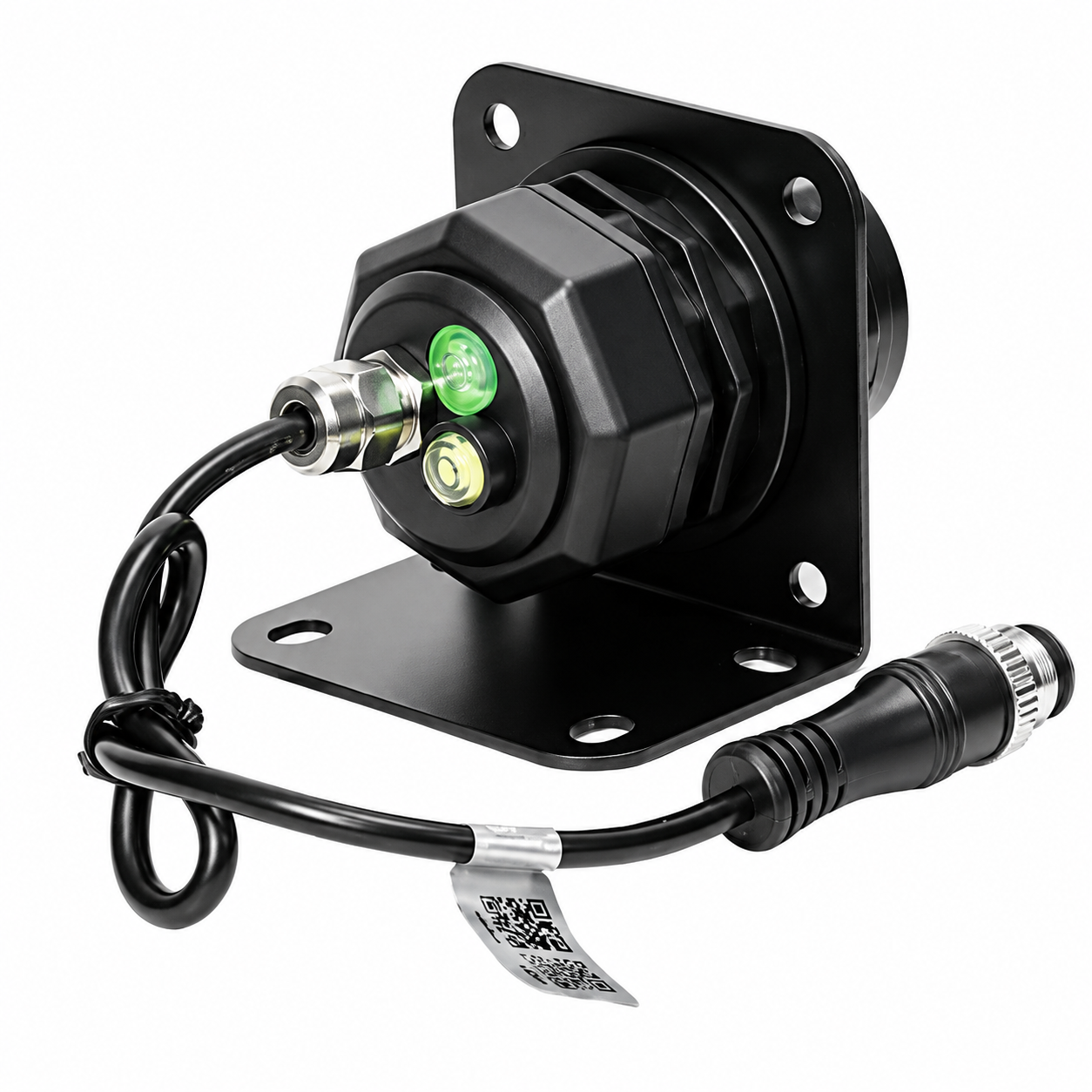
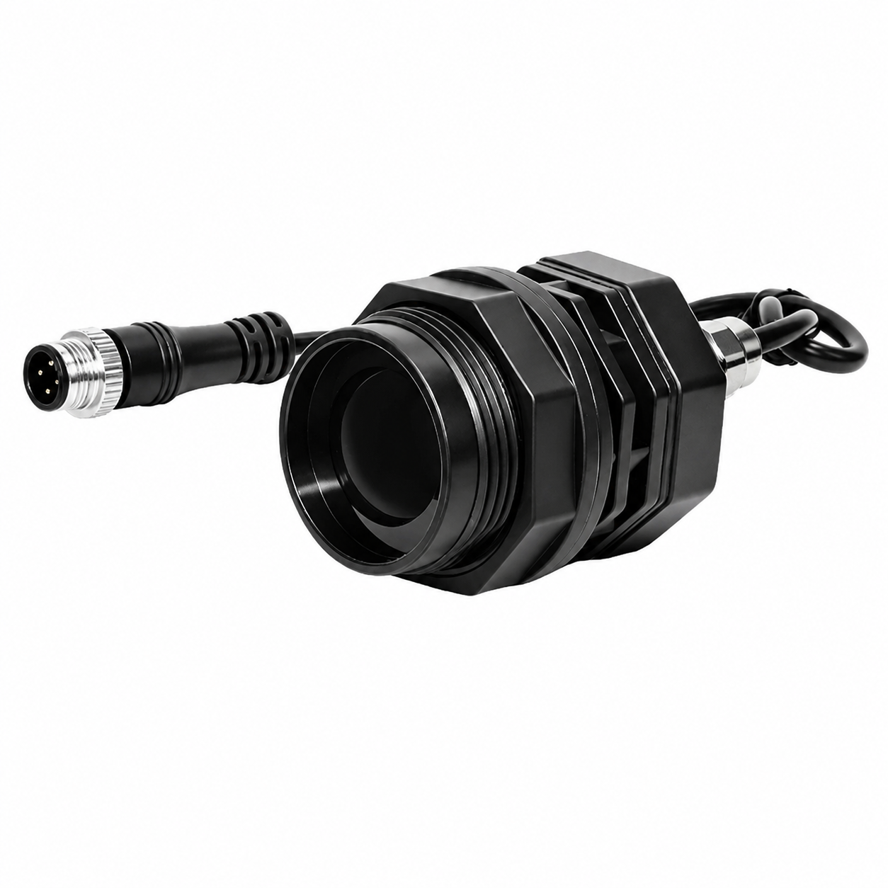
PPK-LD010 Radar Liquid Level Sensor
RS485 FMCW Radar Level Sensor for Industrial Liquid Measurement
The LD010 radar liquid level sensor uses FMCW (Frequency Modulated Continuous Wave) radar technology to achieve accurate and stable non-contact liquid level measurement.
With a compact industrial design, IP68 waterproof protection, RS485 communication, and long-distance detection capability up to 10 meters, it is suitable for water resources, wastewater treatment, storage tanks, chemical processing, and industrial automation applications.
Key Features
1. Long-Distance Detection up to 10m
The LD010 radar level sensor supports a maximum detection distance of 10 meters.
With millimeter-level measurement capability and stable radar signal processing, it provides reliable liquid level monitoring even in challenging environments.
2. FMCW Radar Technology
Adopts FMCW continuous wave radar technology combined with advanced signal processing algorithms.
Advantages:
- Strong anti-interference capability
- Stable measurement in turbulent environments
- Reliable performance under changing conditions
Suitable for applications where traditional contact sensors are difficult to install.
3. High Accuracy & Strong Anti-Interference Performance
The sensor integrates advanced filtering technology to effectively suppress interference signals.
Features:
- High measurement stability
- Excellent electromagnetic interference resistance
- No influence from water vapor, dust, or environmental changes
Supports the 60–64GHz ISM frequency band and complies with FCC and CE standards.
4. Industrial-Grade Waterproof Design
Designed for harsh outdoor and industrial environments.
Features:
- IP68 waterproof protection
- Flame-retardant PP housing material
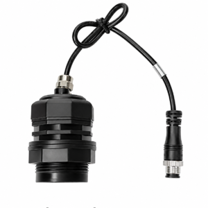
- Aerospace-grade waterproof connector
- Easy installation with mounting bracket
Suitable for long-term outdoor operation.
Applications
The LD010 radar liquid level sensor is widely used in:
Water Reservoirs
Real-time monitoring of water level in reservoirs and water management systems.
Wastewater Treatment Plants
Suitable for sewage tanks and wastewater monitoring.
Liquid Storage Tanks
Used for industrial liquid storage and process control.
Aquaculture Tanks
Supports water level monitoring in farming and breeding systems.
Underground Drainage Systems
Suitable for drainage wells and flood monitoring applications.
Chemical Processing Tanks
Used for liquid level detection in chemical and industrial environments.
Product Specifications
| Parameter | Specification |
|---|---|
| Model | XKC-LD010-RS485 |
| Output Interface | RS485 |
| Communication Protocol | RS485 |
| Detection Range | Up to 10m |
| Working Frequency | 60–64GHz |
| Detection Angle | 10°–13° |
| Response Time | ≤500ms |
| Measurement Accuracy | ±0.1% |
| Power Supply | DC 9V–28V |
| Maximum Power Consumption | <3W |
| Operating Temperature | -40°C ~ +85°C |
| Protection Rating | IP68 |
| Communication Cable Length | Main cable: 500mm / Extension cable: 2000mm (customizable) |
| Connector | M12-4P Waterproof Aviation Connector |
| Housing Material | Flame-retardant PP |
| Certification | CE, RoHS 2.0 |
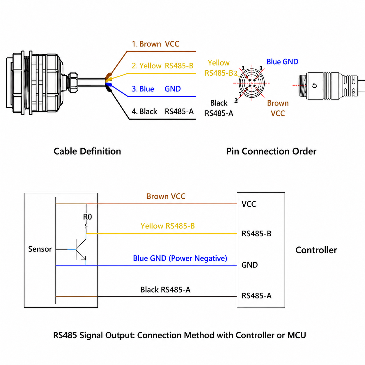
Cable Definition
| Wire Color | Function |
|---|---|
| Brown | VCC (Power Supply) |
| Blue | GND |
| Yellow | RS485-B |
| Black | RS485-A |
Working Principle
The LD010 radar liquid level sensor works based on FMCW radar technology.
The sensor continuously transmits high-frequency radar waves toward the liquid surface. When the radar signal reaches the liquid surface, part of the signal is reflected back to the sensor.
By analyzing the frequency difference between transmitted and received signals, the sensor calculates the distance between the sensor and the liquid surface, allowing accurate liquid level measurement.
Because the radar signal does not require direct contact with the liquid, the sensor is unaffected by:
- Corrosive liquids
- Foam
- Dust
- Temperature changes
- Water vapor
Measurement Method
The LD010 measurement blind zone is 0–15cm.
During measurement:
- Data fluctuations may occur within approximately ±5cm around the target area.
- Response time may vary between approximately 0.5s–2s depending on application conditions.
For optimal measurement accuracy:
- The detected target should be within the effective detection range.
- The signal path should remain unobstructed.
The effective detection distance depends on the detection angle and installation environment.
Package Contents
Standard package includes:
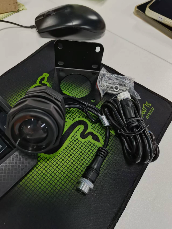
- Radar level sensor ×1
- Extension cable ×1
- Mounting bracket ×1
- Screws ×1 set
- PE protection bag ×1
- Packaging box ×1
Installation Notes
To ensure accurate and stable radar level measurement, please follow the installation guidelines below:
1. Ensure Clear Radar Signal Transmission
The radar antenna should be aligned directly toward the measurement area.
Keep the area around the antenna free from obstacles to avoid signal blockage or reflection interference.
2. Ensure Stable Installation
The sensor must be installed firmly and securely.
Any movement or vibration of the radar sensor may affect measurement accuracy and stability.
3. Avoid Moving Objects Behind the Sensor
The area behind the radar sensor should be free from moving objects or vibration sources.
Since radar waves have penetration characteristics, objects behind the sensor may generate reflected signals and affect measurement results.
For applications with unavoidable background interference, a metal shielding plate or metal backplane can be installed to reduce unwanted reflections.
4. Measurement Accuracy Considerations
Radar theoretical distance accuracy is based on physical resolution and advanced algorithm processing.
Due to factors such as:
- Floating objects on the liquid surface
- Wave fluctuations
- Liquid turbulence
Actual measurement values may have slight variations.
RS485 Communication Protocol
1. Modbus Protocol Introduction
The LD010 radar level sensor supports the standard Modbus RTU communication protocol.
Supported Function Codes:
| Function Code | Description |
|---|---|
| 03H | Read Holding Registers |
| 06H | Write Single Register |
| 10H | Write Multiple Registers |
Address Definition
- Slave address: 1 byte
- Broadcast address: 0
- Slave address range: 1–247
- Reserved address: 248–255
Communication Parameters
Default communication settings:
| Parameter | Value |
|---|---|
| Baud Rate | 9600 bps |
| Data Bits | 8 bits |
| Parity | None |
| Stop Bits | 1 bit |
CRC Verification
CRC uses 2 bytes.
Little-endian mode.
Verification range:
Slave Address + Function Code + Data Area
Modbus Address Description
Modbus addresses are normally based on starting from 1, while many MCU systems use addresses starting from 0.
Therefore:
- Some PLC systems may require address offset adjustment.
- Some master devices automatically subtract 1.
- Please confirm address settings during integration.
Communication Function Codes
| Function Code | Exception Code | Description | Operation |
|---|---|---|---|
| 03H | 83H | Read Holding Registers | Read single or multiple registers |
| 06H | 86H | Write Single Register | Write one register |
| 10H | 90H | Write Multiple Registers | Write multiple registers |
Register Address Map
| Register Address | Function | Data Range | R/W |
|---|---|---|---|
| 0001H | Set Slave ID | 0 = Broadcast, 1–247 = Slave Address | R/W |
| 0011H | Read Distance Data | Unit: mm | R |
| 0012H | Calibration Command | 0000 | W |
| 0013H | Distance Upload Mode | 0000 Auto Upload / 0001 Manual Upload | R/W |
| 0014H | Buzzer Enable | 0000 Disable / 0001 Enable | R/W |
| 0015H | Baud Rate Setting | 01–08 | R/W |
| 0016H | Restore Default Settings | Write 0001 Restore | W |
| 0017H | System Status | Bit Status Information | R |
| 0018H | Calibration Reference Distance | 0–10000 mm | R/W |
| 0019H | Sensor Detection Distance | 0–10000 mm | R/W |
| 001AH | Empty Distance | Unit: mm | R/W |
| 001BH | Output Liquid Level Height | Unit: mm | R |
| 001CH | Liquid Level Calibration Value | Unit: mm | R/W |
| 001DH | Upgrade Flag | Reserved | R/W |
| 001FH | Calibration K Value | 10000 Corresponds to 1 | R/W |
| 0020H | Radar Reference Distance Offset | Unit: mm | R/W |
| 0021H | Current Distance Value | Unit: mm | R |
Baud Rate Selection
| Code | Baud Rate |
|---|---|
| 01 | 1200 |
| 02 | 2400 |
| 03 | 4800 |
| 04 | 9600 |
| 05 | 19200 |
| 06 | 38400 |
| 07 | 57600 |
| 08 | 115200 |

eal-time river level monitoring, all-weather accuracy even in heavy rain.