
简介视频
Changelog #
- 22025-11-5:
- Firmware v1.3.3:
- Fixed the issue of screen corruption (garbled display) occurring after the reflow process has finished.
- Firmware v1.3.3:
- Firmware v1.3.3:
- Fixed the issue of screen corruption (garbled display) occurring after the reflow process has finished.
- 2025-10-20:
- Firmware v1.3.2:
- Optimized display efficiency; user interface operations are no longer sluggish.
- In Reflow Soldering Mode: The duration of the reflow phase can now be configured, and a target temperature can be set for the cooling phase; the cooling fan will stop once this target temperature is reached.
- Circuitry: The position of capacitor C39 on the power board has been shifted slightly upward to prevent potential physical interference with the control board’s pin headers. In older versions, the pin headers and this capacitor were positioned almost in direct contact; during assembly, this could be resolved by soldering the capacitor with a slight offset to the left.
- 2025-10-8:
- Firmware v1.2.2: Adjusted the fan activation threshold; the cooling fan now only activates when the current temperature exceeds the target temperature by 6°C.
- Circuitry: Fixed a bug on the power board and optimized the PCB layout for the power board.
- 2025-9-8: v1.2.1: Fixed an issue where temperature readings would occasionally return erroneous values.
- 2025-9-1: v1.2.0: Added a temperature calibration feature. If significant temperature discrepancies are observed after assembly, independent temperature calibration offsets can now be set specifically for the 50°C and 200°C points.
- 2025-8-26: Some users reported issues with their rotary encoders having reversed rotation directions, inverted screen colors, or display coordinate offsets. The new firmware version (v1.1.0) introduces a settings menu allowing users to configure the encoder rotation direction, toggle screen color inversion, and adjust the display coordinate positioning.
- 2025-8-18: To ensure compatibility with certain types of rotary encoders, the spacing between the control board and the device enclosure was increased. However, this modification inadvertently created a physical conflict between the control board and the cooling fan connector on the power board. This issue has now been resolved by shifting the positions of the two XH2.54 connectors located on the underside of the control board slightly upward.
Project Rationale #
I got into electronics design this past March. So far, I’ve built a serial downloader module, an STC8H core board, a charging module for a handheld vacuum cleaner, and an ATX power supply adapter board; this marks my fifth PCB project.
While I purchased my soldering iron and hot air gun as off-the-shelf units, after disassembling them to study their internals, I decided I’d like to try building a heating station myself—and thus, this project was born. Given its red color and the intense heat it generates, I’ve named it the “Red Dragon Heating Station”—a tribute to Firkraag, the famous Red Dragon from Baldur’s Gate.
I’m still a beginner, so I welcome any and all feedback!
Below are some of the design considerations I took into account before beginning the build:
- My goal is to build a low-cost, aesthetically pleasing heating platform—complete with a reflow soldering temperature profile—specifically designed for soldering PCBs.
- By employing a stacked structural design, I aim to keep the overall height as low as possible to ensure maximum convenience during use.
- To enhance safety, I intend to house the wiring and cooling fan—located beneath the heating plate—entirely within the enclosure, thereby minimizing any exposed components.
- The software will be feature-rich, allowing for the configuration of various parameters to ensure maximum adaptability across a wide range of scenarios.
- This project is guided by pragmatic principles: while ensuring that all functional requirements are fully met, I will strive to keep costs to a minimum, avoiding the inclusion of any gratuitous or gimmicky features.
- I currently have just one remaining STC8H1K08 microcontroller on hand; once I’ve cleared out my remaining stock, I plan to transition my future projects to the ARM platform.
- Admittedly, the 8KB of Flash memory is quite restrictive. However, considering that this project essentially boils down to a temperature control system, I am confident that—leveraging my 30 years of coding experience and by thoroughly optimizing the code—the “National Treasure” STC8H1K08 is more than capable of successfully completing this project.
Open Source License #
Hardware Components: Licensed under the Creative Commons “CC-BY-NC-SA 4.0” license. Please do not use for commercial purposes; if republishing, please attribute the source.
Software Component: https://github.com/elisaday/firkraag-reflow-hot-plate
This section is licensed under the MIT License—arguably the most permissive license available—meaning you are free to use and handle the code however you wish.
Project Introduction #
12V Version #
I opted for a power supply solution utilizing a repurposed ATX power supply unit. For the MCH ceramic heating element, I purchased a 1-ohm version with a theoretical power output of 144 watts. My reasoning was that since the 65-watt PD-powered heating platforms—(I hadn’t realized at the time that they measured 50 x 50mm)—worked just fine, my 144-watt setup should certainly be adequate, even after accounting for the increase in the MCH element’s resistance as its temperature rose. Consequently, I placed a CNC order for an aluminum plate measuring 80 x 80 x 3.5mm.
However, I overlooked a critical factor: the thermal capacity of the aluminum plate.
Since the generic ATX power supply I used was of rather poor quality to begin with, once the unit heated up past 150°C—and as the MCH element’s resistance increased—the actual measured power output dropped to less than 80 watts. For an aluminum plate measuring 80 x 80 x 3.5mm, this meager power output of just a few dozen watts proved to be woefully insufficient.
Following this failure, I wrote a simple script to calculate thermal capacity. To make the tool more user-friendly, I enlisted the help of AI to wrap the script in a web-based user interface.
The calculation script utilizes two data samples sourced from: https://oshwhub.com/cqlcp/adjustable-timing-constant-temperature-heating-table
Many thanks to the original author for sharing this valuable data.
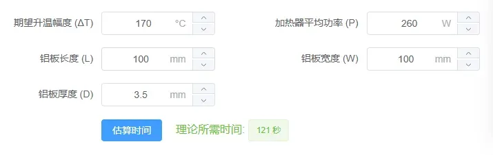
In the 12V version, at a temperature of 180°C, the resistance of the 1-ohm MCH element rises to 1.6 ohms. Based on this ratio, in the 220V version, a single 230-ohm MCH heating element has a power output of 130W; therefore, two such elements would yield a total of 260W.
Rising from 30°C to 200°C in 121 seconds, it essentially meets the requirements.
Structural Section #
This section requires consideration of thermal insulation to prevent heat from conducting downwards.
- The top surface consists of a CNC-machined aluminum plate, currently measuring 100 x 100 mm. If ordered through JialiChuang, the cost—including shipping directly to your doorstep—is approximately 10 RMB, making it an extremely cost-effective option.
- Embedded within the aluminum plate are two 15 x 70 mm MCH ceramic heating elements, each with a resistance of 230 ohms and a combined rated power of 420 W.
- The aluminum plate is secured to the extension nuts using set screws; this arrangement ensures the centers of the extension nuts remain hollow, thereby minimizing heat transfer.
- The aluminum plate is mounted in an inverted configuration onto the aluminum alloy enclosure, utilizing M3 extension nuts (made of 304 stainless steel) and flat mounting brackets (made of 301 or 304 stainless steel). Notably, the nuts do not make direct contact with the aluminum alloy enclosure. This inverted mounting structure was inspired by the design found at: https://oshwhub.com/coolouba/hui-liu-han-jia-re-tai. Many thanks to the original author for open-sourcing their work.
#
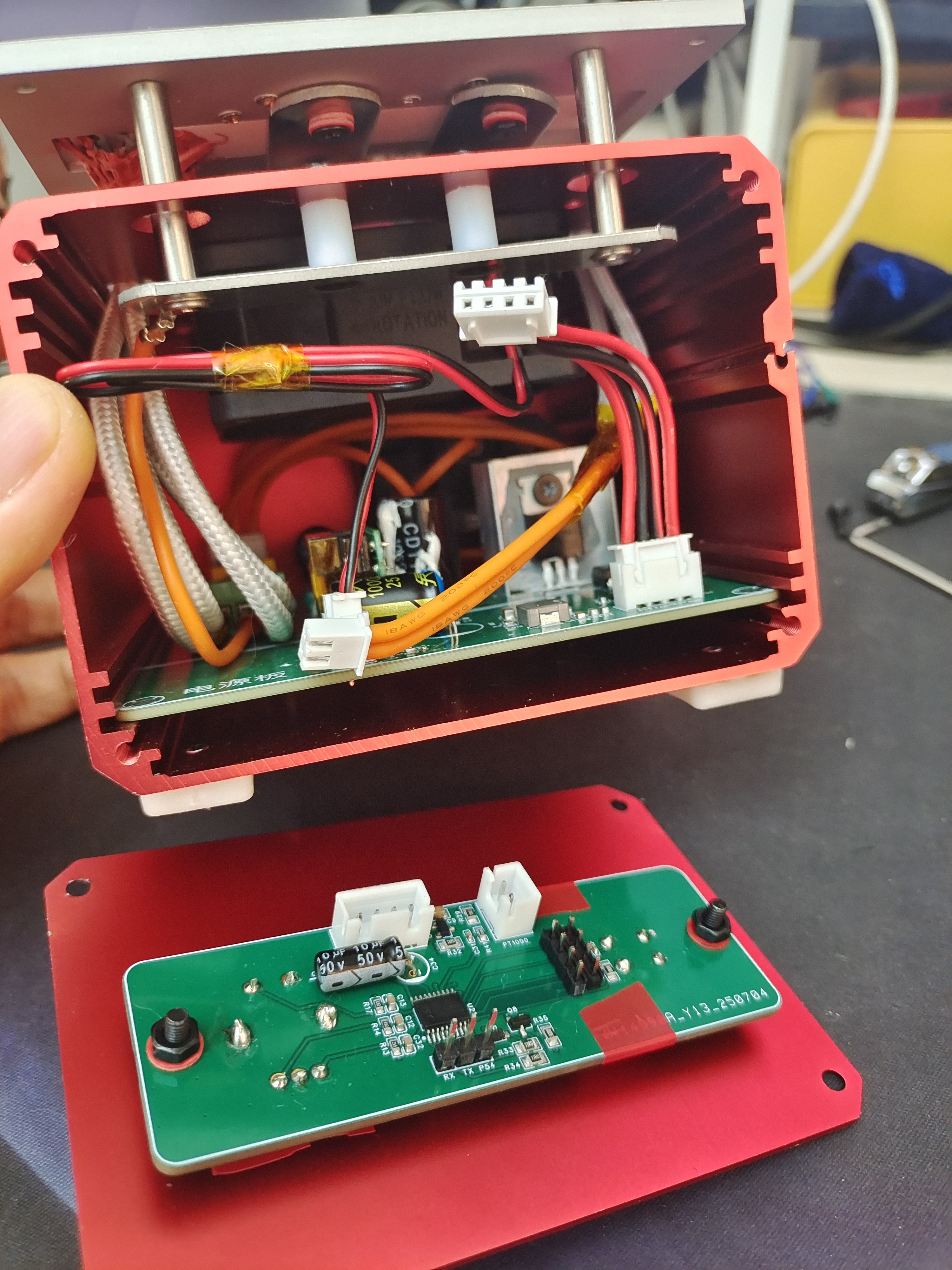
Circuit #
Power Board #
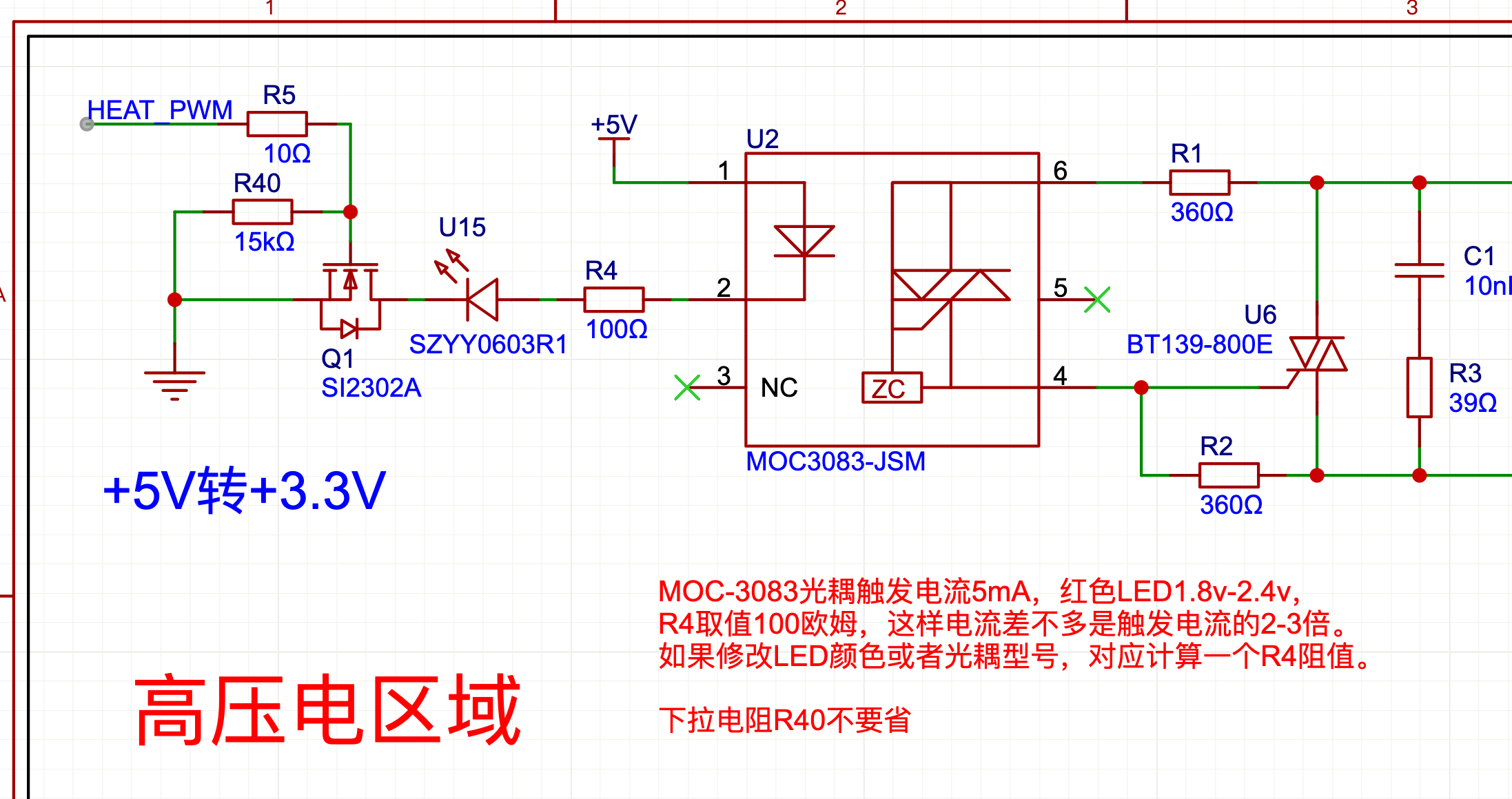
- I adapted the SCR control circuit section directly from the “Zhaoyang” heating station project. However, since this project is split across two PCBs—a power board and a control board—I encountered an issue with spurious triggering of the SCR while independently debugging the power board. Consequently, I added a pull-down resistor to the MOSFET situated at the SCR optocoupler stage.
- Additionally, I wired a red LED in series with the optocoupler’s internal LED current path to serve as a visual indicator of the heating status.
#
#
- For the fan, I selected a 6-inch cooling fan rated at 12V and 0.38A; under actual testing at 12V, it draws 0.3A. Since the startup current exceeds 0.6A, I opted for a 10W model for the 220V-to-12V power conversion module.
- The 12V output is stepped down to 5V via a DC-DC converter, and subsequently stepped down to 3.3V using an LDO regulator.
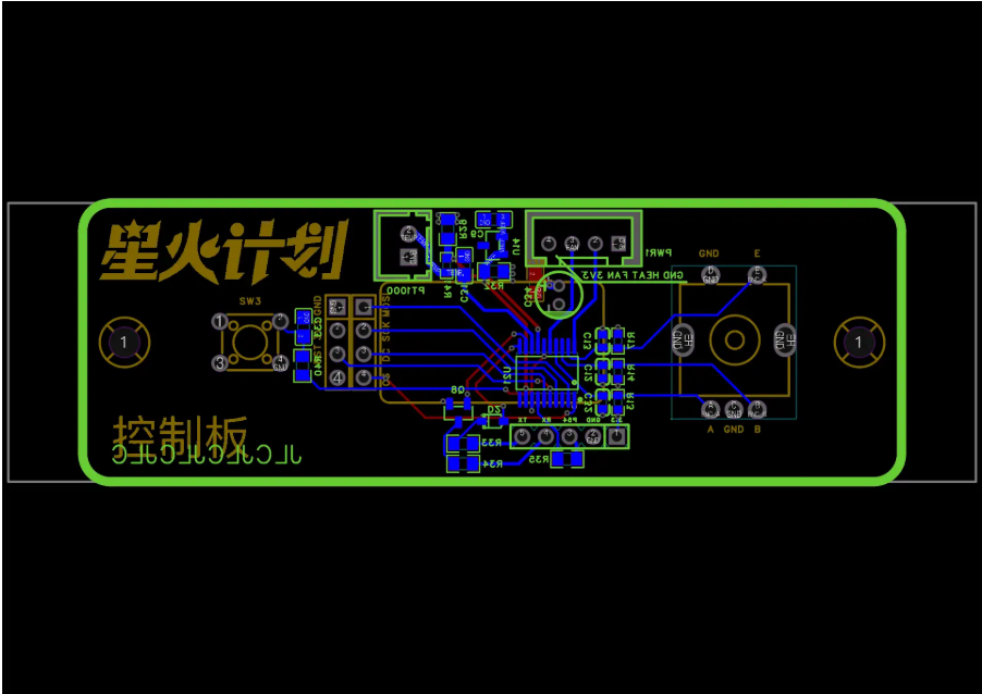
Control Board #
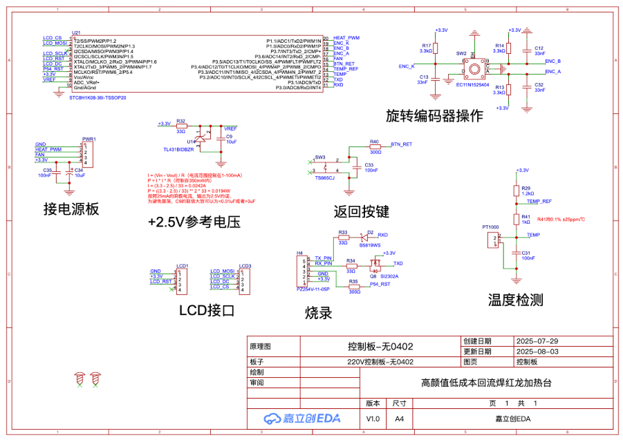
This section primarily covers:
- EC11 Rotary Encoder
- Return Button
- LCD Screen Interface
- Microcontroller Programming Circuit
- PT1000 Sampling Circuit
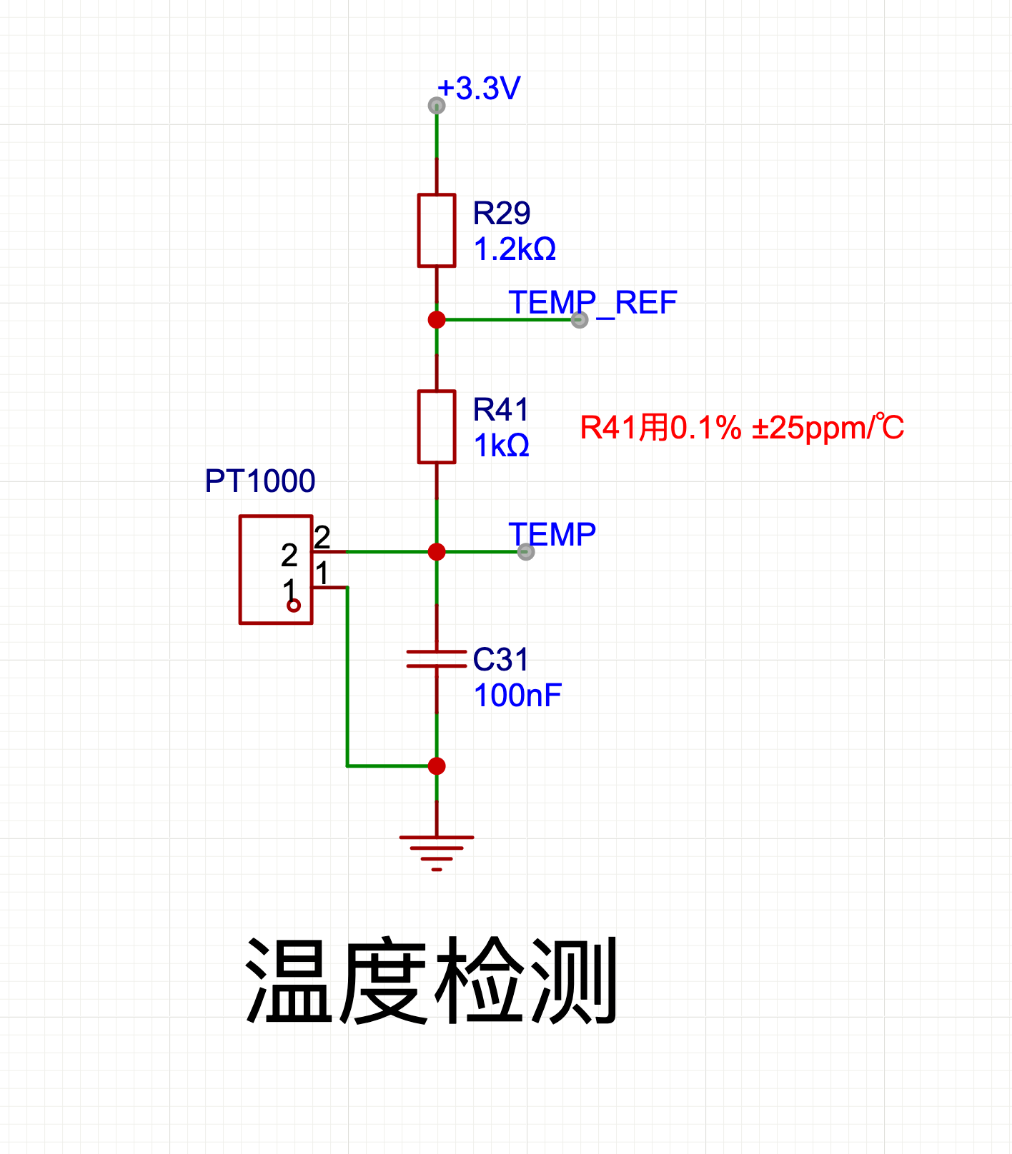
The ingenuity of this method lies in the fact that the final measured voltage value is independent of the supplied +3.3V reference; consequently, even if the +3.3V supply fluctuates, it does not affect the measurement accuracy. Note that R41 must be a high-precision resistor with a low temperature coefficient. R29, serving as a voltage divider resistor, is assigned a value of 1.2 kΩ; this specific value is chosen to ensure that the measured output falls within the 2.5V range—thereby maximizing the effective measurement span while still maintaining a sufficient operational margin.
Software Components #
Since I had virtually no prior experience programming 51-series microcontrollers—and was generally unfamiliar with this specific chip—utilizing a Hardware Abstraction Layer (HAL) library was a particularly user-friendly approach for me. Consequently, I initially adopted the libfw_stc8 library; my sincere thanks go to the author for making it open source.
Once I had completed functional testing of the core code modules, I turned my attention to optimizing code size. At that point, libfw_stc8 could be retired (a classic case of “burning one’s bridges after crossing the river”). Ultimately, I retained only a very small subset of libfw_stc8‘s macro and type definitions.
Function #
The currently completed feature map is as follows:
- Reflow Soldering Mode
- Set Parameters for Each Reflow Stage
- Start Reflow Soldering
- Constant Temperature Mode
- Set Target Temperature
- Start Constant Temperature Mode
- Settings
- Configure PID Parameters (Proportional, Integral, Derivative, Delay)
- Press the Back Button in the Main Menu to Force-Enable the Fan
Size Optimization #
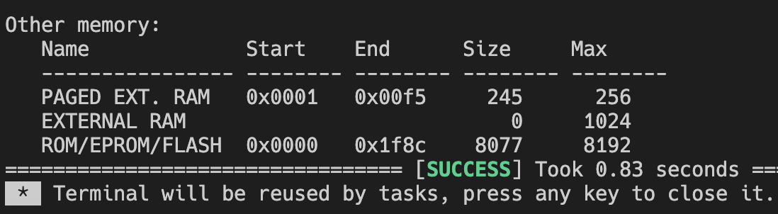
Ultimately, out of the 8,192 bytes of available space, approximately 8,077 bytes were utilized, leaving a remainder of a few dozen bytes; the paging pseudo-stack consumed 245 bytes.
However, there are still some areas in the code that could be optimized; it is entirely possible to further reduce the Flash memory footprint to approximately 7,800–7,900 bytes. Doing so would actually allow for further improvements to the user experience—interested readers are encouraged to give it a try themselves.
To briefly summarize the optimization:
- Overhead introduced by the HAL library. This section addresses this by directly removing HAL library functions and fully expanding all macros into their most concise forms.
- Relocating font data to the EEPROM.
Implementing these two measures results in significant space savings. However, given the control requirements of this specific project, these optimizations are still far from sufficient.
Further optimization is still required regarding both stack space and program storage usage.
Regarding that 256-byte pseudo-stack, the primary focus should be on static variables and function definitions.
As for the program space, the main concern is whether the implemented logic is concise.
- Review all static variables; use 8-bit types whenever possible instead of 16-bit ones. This is a straightforward task.
- Avoid using return values for functions whenever feasible.
- Keep function parameters to a minimum, and use the smallest possible data types for them.
- When writing logic, aim for maximum simplicity and directness; avoid convoluted constructs that might hinder compiler optimizations.
- Write code that closely mirrors the output generated by the compiler—for instance, by making judicious and necessary use of
gotostatements to provide optimization hints to the compiler. - To ensure code conciseness, certain compromises regarding interaction design may be required.
Temperature Control PID Algorithm #
When implementing a temperature control PID algorithm for the first time, I made a point of studying the underlying principles. The theory is actually quite straightforward—similar algorithms are commonly used for motion control in game development. However, after implementing it, I noticed a persistent delay in the temperature readings; I suspect this is due to improper installation of my PT1000 sensor.
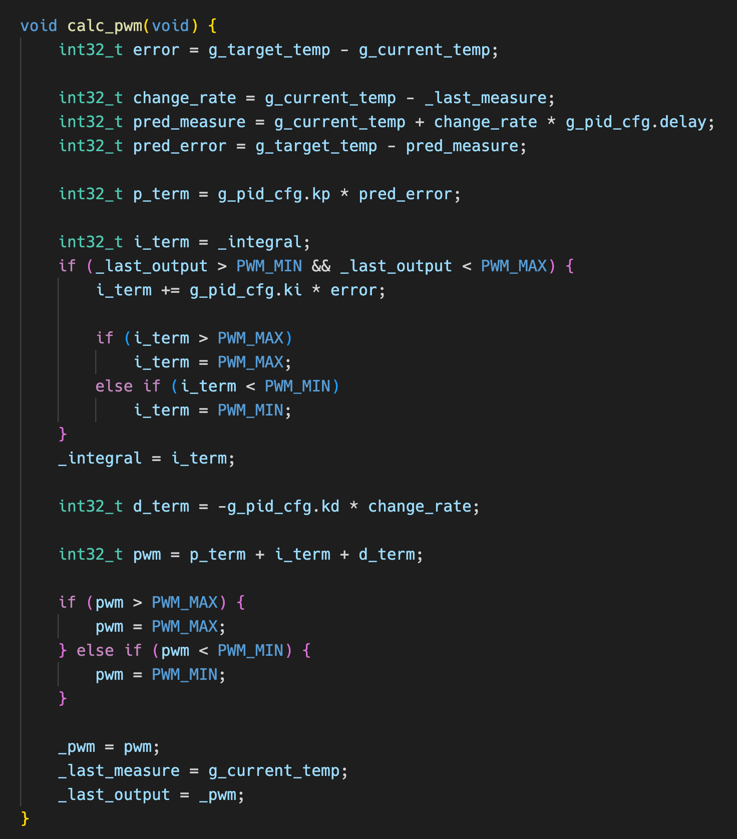
Consequently, I added a delay parameter to the algorithm. The objective is to estimate future temperature rise based on historical rates of temperature increase, and subsequently perform error estimation based on these predicted values.
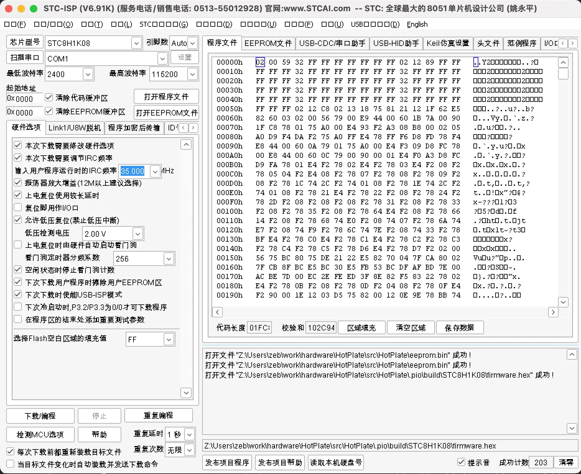
Firmware Download Parameters #
Replication Considerations #
- This project involves 220V mains electricity; please exercise extreme caution when replicating it and ensure that proper insulation and safety precautions are in place.
- Before powering on the device, inspect all solder joints to verify that there are no cold joints or short circuits. Ensure that the enclosure, the aluminum heating plate, and all other accessible surfaces are properly grounded.
Schematic Diagram
PCB
BOM
| ID | Name | Designator | Footprint | Quantity | Manufacturer Part | Manufacturer | Supplier | Supplier Part |
|---|---|---|---|---|---|---|---|---|
| 1 | 33nF | C32,C12,C13 | C0603 | 3 | CC0603KRX7R9BB333 | YAGEO(国巨) | LCSC | C106856 |
| 2 | EC11N1525404 | SW2 | SW-TH_EC11NXXXX | 1 | EC11N1525404 | ALPSALPINE(阿尔卑斯阿尔派) | LCSC | C470748 |
| 3 | ZX-XH2.54-2PZZ | PT1000 | CONN-TH_2P-P2.50_HX25003-2A | 1 | ZX-XH2.54-2PZZ | Megastar(兆星) | LCSC | C7429632 |
| 4 | 100nF | C31,C33,C35 | C0805 | 3 | 0805B104K500NT | FH(风华) | LCSC | C38141 |
| 5 | 1.2kΩ | R29 | R0805 | 1 | 0805W8F1201T5E | UNI-ROYAL(厚声) | LCSC | C17379 |
| 6 | 33Ω | R33,R34,R32 | R0805 | 3 | 0805W8F330JT5E | UNI-ROYAL(厚声) | LCSC | C17634 |
| 7 | SI2302A | Q8 | SOT-23-3_L2.9-W1.3-P1.90-LS2.4-BR | 1 | SI2302A | UMW(友台半导体) | LCSC | C347483 |
| 8 | B5819WS | D2 | SOD-323_L1.8-W1.3-LS2.5-RD | 1 | B5819WS | CJ(江苏长电/长晶) | LCSC | C22624 |
| 9 | 300Ω | R35,R40 | R0805 | 2 | 0805W8F3000T5E | UNI-ROYAL(厚声) | LCSC | C17617 |
| 10 | STC8H1K08-36I-TSSOP20 | U21 | TSSOP-20_L6.5-W4.4-P0.65-LS6.4-BL | 1 | STC8H1K08-36I-TSSOP20 | STC | LCSC | C915673 |
| 11 | TL431BIDBZR | U14 | SOT-23-3_L2.9-W1.3-P1.90-LS2.4-BR | 1 | TL431BIDBZR | TI(德州仪器) | LCSC | C41283 |
| 12 | 10uF | C9 | C0805 | 1 | CL21A106KOQNNNE | SAMSUNG(三星) | LCSC | C1713 |
| 13 | ZX-XH2.54-4PZZ | PWR1 | CONN-TH_4P-P2.50_4PIN | 1 | ZX-XH2.54-4PZZ | Megastar(兆星) | LCSC | C7429634 |
| 14 | 3.3kΩ | R17,R14,R13 | R0603 | 3 | 0603WAF3301T5E | UNI-ROYAL(厚声) | LCSC | C22978 |
| 15 | M3螺丝 | SCREW1,SCREW2 | M3螺丝 | 2 | ||||
| 16 | PZ254V-11-04P | LCD1,LCD3 | HDR-TH_4P-P2.54-V-M | 2 | PZ254V-11-04P | XFCN(兴飞) | LCSC | C2691448 |
| 17 | TS665CJ | SW3 | SW-TH_4P-L6.0-W6.0-P4.50-LS6.5 | 1 | TS665CJ | SHOU HAN(首韩) | LCSC | C393938 |
| 18 | 1kΩ | R41 | R0603 | 1 | RT0603BRD071KL | YAGEO(国巨) | LCSC | C110776 |
| 19 | 10uF | C34 | CAP-TH_BD5.0-P2.00-D0.8-FD | 1 | ERS1HM100D11OT | AISHI(艾华集团) | LCSC | C106654 |
| 20 | PZ254V-11-05P | H4 | HDR-TH_5P-P2.54-V-M | 1 | PZ254V-11-05P | XFCN(兴飞) | LCSC | C492404 |


