1.Introduction/History #
Since the beginning of the 20th century when music carriers entered public life, their forms have continuously evolved with technological innovations, and each change has reshaped the way people listen to and spread music.
1. Black glue – simulation #
- In the 1950s, vinyl records (LP, Long Play) recorded sound through their physical grooves, representing the pinnacle of analog technology. However, vinyl is bulky, fragile, and has limited capacity
2. Magnetic Tape – Portable #
- The emergence of cassette tapes in the 1960s completely changed the music consumption scene. The lightweight and easy to carry nature of magnetic tapes allows music to break away from home audio systems and enter cars, Walkmen, and outdoors.
3. CD – Sound Quality #
- The birth of Compact Disc (CD) in 1982 marked the comprehensive digitization of music media. CDs store audio digitally, providing noise free sound quality and digital fast forward functionality, quickly replacing vinyl and magnetic tapes.
4. MP3 and Streaming Media – Disruption #
- At the beginning of the 21st century, MP3 players and smartphones ushered in a digital music revolution, Spotify、Apple Music、 NetEase Cloud Music and other streaming platforms have completely deconstructed the concept of physical carriers. Users only need to tap their fingers to hear songs from any singer or band. Streaming media has lowered the threshold for music distribution.
And magnetic tape played a pivotal role in music history, pioneering portable music.
size #
The size of cassette tapes is much smaller than many modern mobile phones, and they are not as bulky as vinyl tapes used to be. When cassette tapes first came out, the playback devices were still very bulky, and many people even carried a tape recorder on the streets. And later on, playback devices became smaller and smaller, especially after the release of Sony Walkman, which was only the size of current mobile phones.
The Torrent of the Times #
Although cassette tapes became progressively smaller and more portable over time, they were ultimately drowned out in today’s vast ocean of streaming media. Their electro-acoustic performance parameters—such as signal-to-noise ratio—fall short of those of CDs, and even modern streaming services. Consequently, cassettes have now become a hobby enjoyed by only a small niche of enthusiasts.
Tape Technology #
Tape technology, for all intents and purposes, is on the verge of becoming a lost art. Within the audio industry, aside from the engineers who worked with tape back in the day, virtually all of today’s newcomers focus exclusively on digital audio, steering clear of such obsolete technologies.
Therefore, I have specifically undertaken this project to provide a detailed explanation of cassette tape technology, construct a simple tape playback circuit, and assemble the finished device.
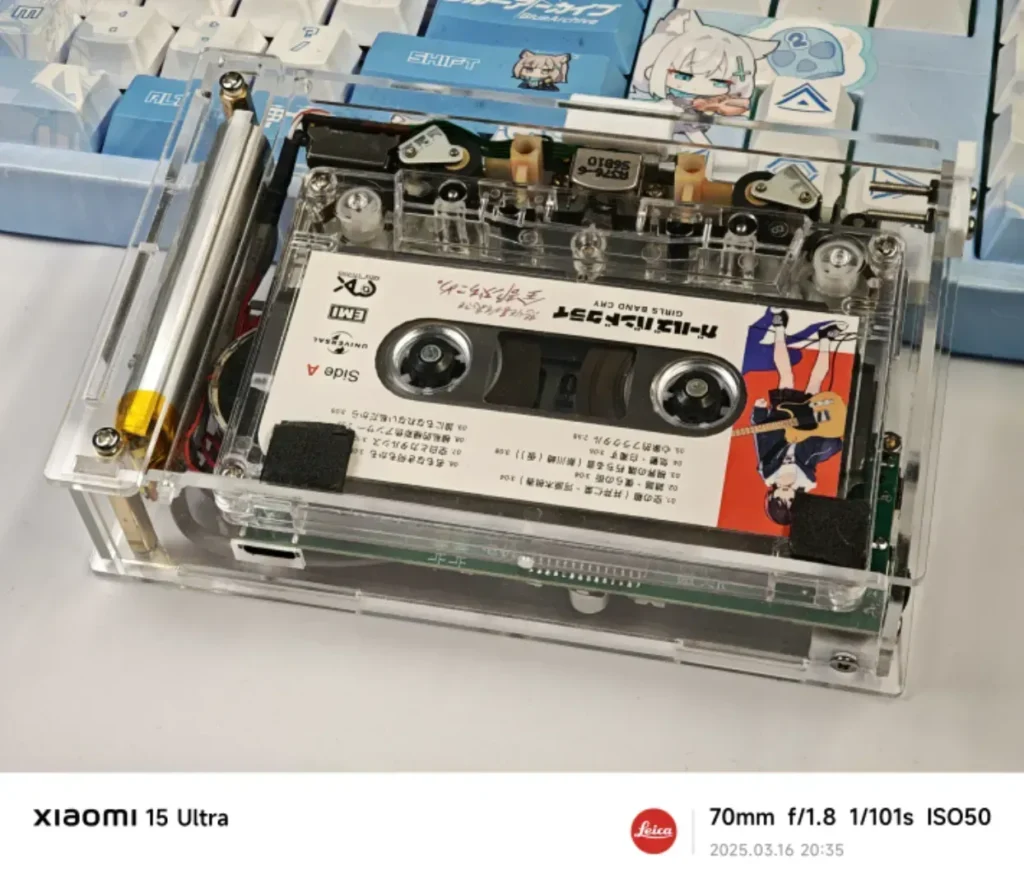
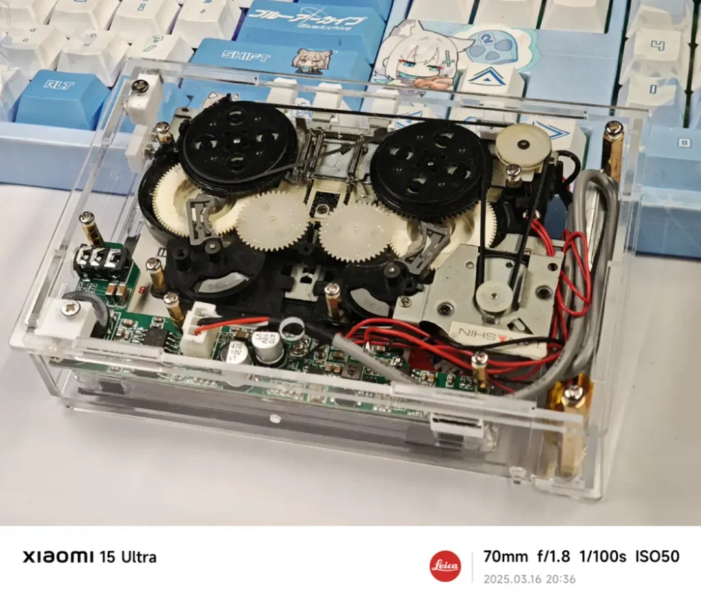
This project utilizes the LAG668 for magnetic head amplification and motor EQ control, and the CXA1552M as a Dolby B-type noise reduction processor, creating a portable cassette player complete with lithium battery charge/discharge management and an auto-reverse function. The casing is constructed from acrylic, allowing the internal mechanical components—such as the gears and motor—to be seen in motion, resulting in a truly beautiful aesthetic. (This is likely the first cassette-based project to appear on this open-source platform.)
2.block diagram #
The circuit is quite simple; the audio path consists of just a single head amplifier and a noise reduction stage. Each corresponding chip is supplied with precisely the power it requires.
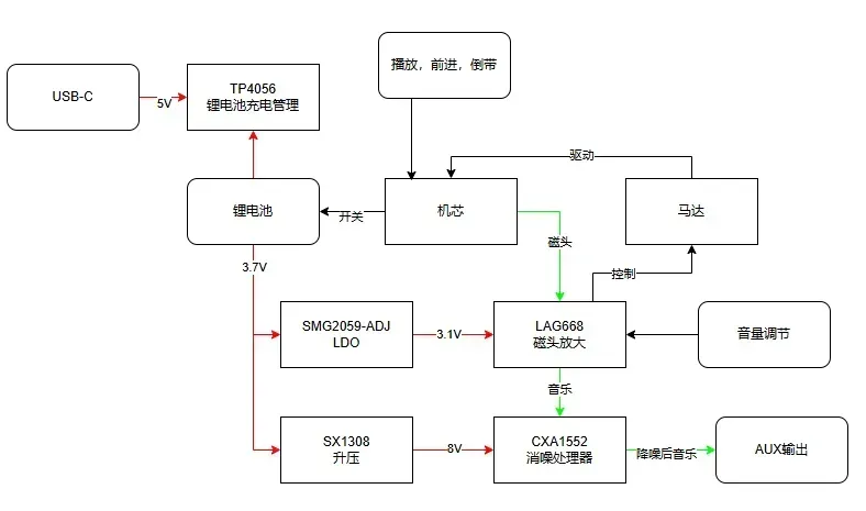
The LDO model in the block diagram is mislabeled; it should be SGM2059-ADJ.
3.Circuit Schematic #
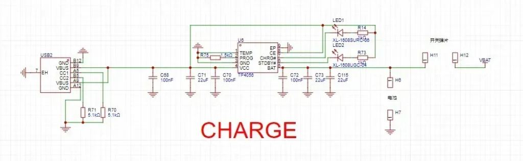
Charging Circuit #
The charging circuit utilizes a standard, widely used TP4056-based linear charging topology. Solder points are used in place of the battery and contact springs.
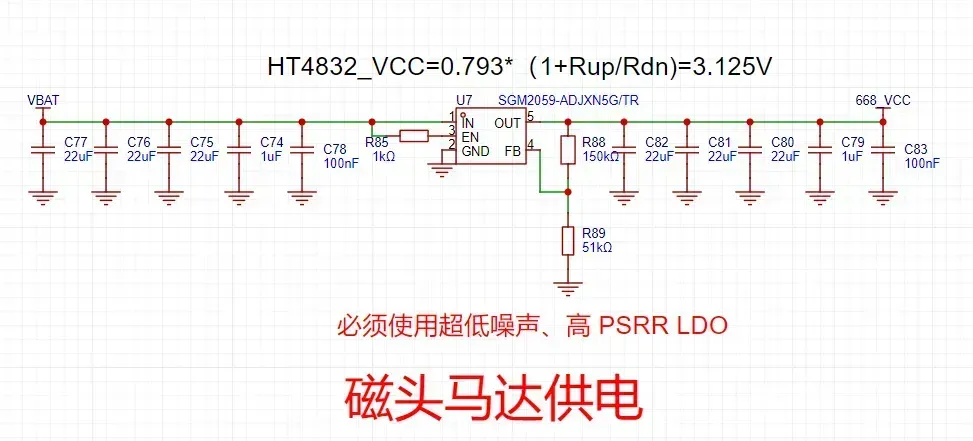
LDO #
The SGM2059-ADJ is an ultra-low-noise, high-PSRR LDO with an adjustable output—regulated at approximately 3.125V—designed to power magnetic head amplifier chips and motors.
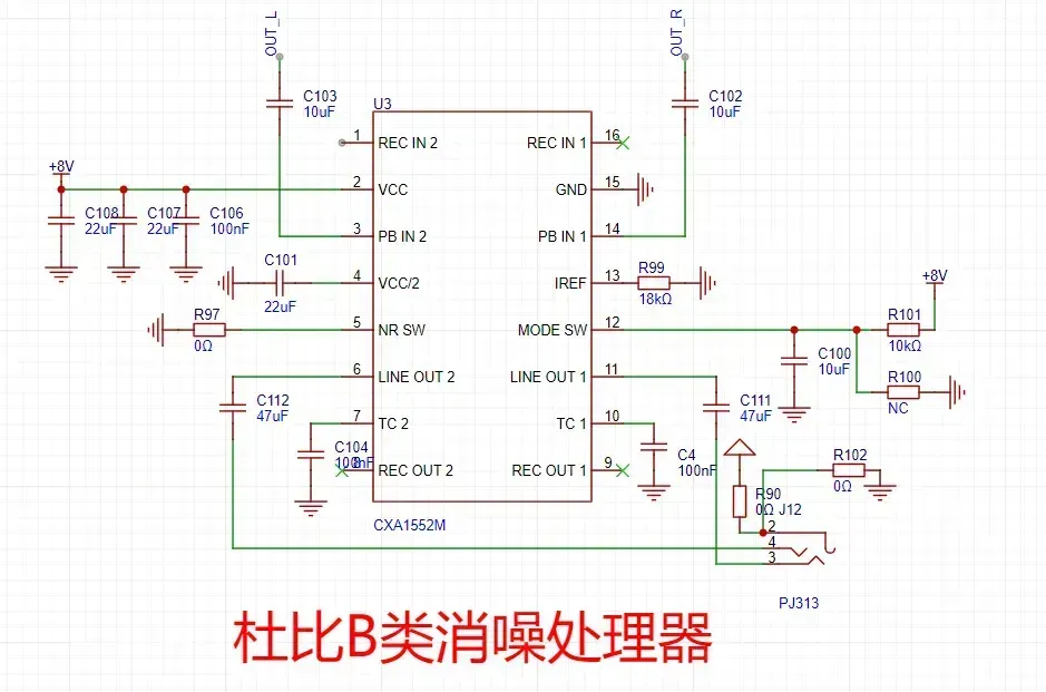
Dolby Noise Cancellation #
The CXA1552 is a Sony Dolby Type B noise reduction processor; it operates on a supply voltage of 6.5 to 23 V and outputs audio after applying noise reduction to the analog audio input.
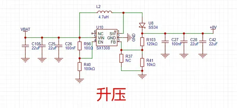
Voltage Boosting #
A boost converter IC designed to step up battery voltage to 8V, specifically intended for use with the CXA1552.
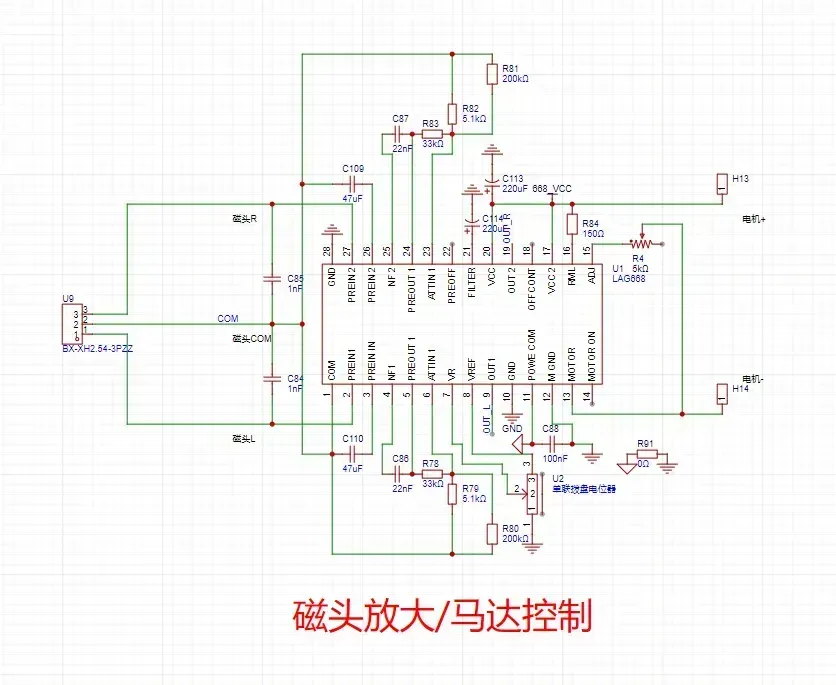
Head Amplification #
LAG668 Head Amplifier and EQ Processor, featuring Motor Control, Tape Speed Adjustment, and Volume Control.
4.LAYOUT #
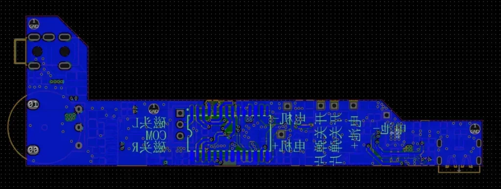
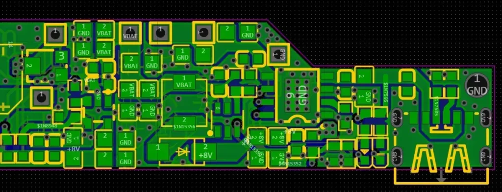
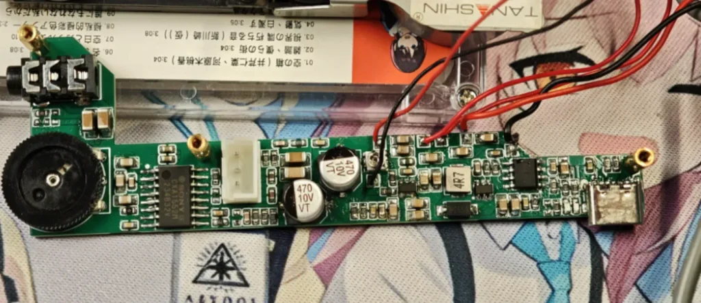
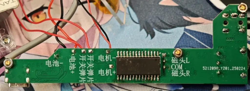
Since the entire circuit board must be positioned beneath the drive mechanism, the component layout is quite dense; the primary components are located on the front side, while the read/write head control chip is situated on the back.
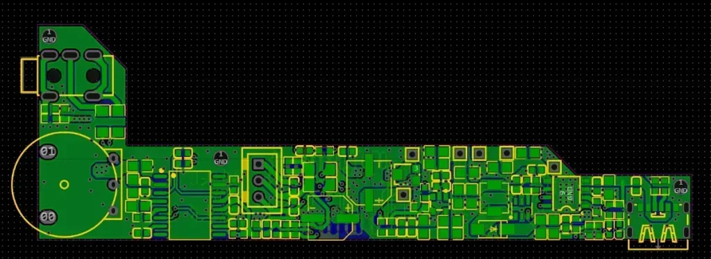
The components are dense and compact, so a 4-layer PCB layout was used; the dimensions measure exactly 10 cm, allowing me to take advantage of JLCPCB’s free manufacturing offer.
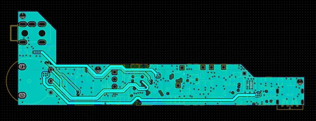
The primary objective for the entire board is to ensure that the analog signals remain free from interference.
Analog signals can be routed on the inner layers.
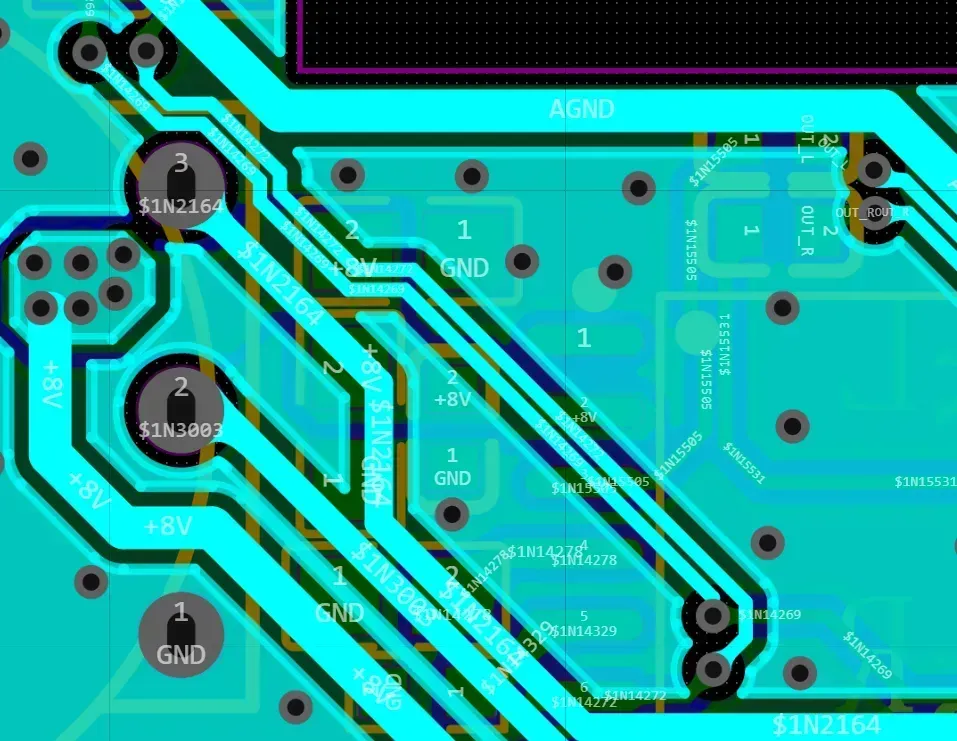
Power supplies—particularly boost converters—generate significant interference; therefore, they should be placed as far away as possible from the analog signal section.
5.Purchase Components #
Movement #
Shielded Wire
Wire (22 AWG)
Assembly Screws & Nuts
M2.3 × 5 Self-tapping Screws
Brass Standoffs
M2 × 2 + 3 (For Movement)
M2 × 8 + 3 (For PCB)
Brass Standoffs
M2.5 × 27 (For Housing)
Screws
M2 × 4 (For Assembly)
M2.5 × 6 (For Mating with M2.5 × 27 Standoffs)
M2 × 16 (For Assembly)
M2 Nuts
For Maintenance
Drive Belt
Lubricating Grease / Oil
6.Purchase Components #
Movement, Battery, Mainboard
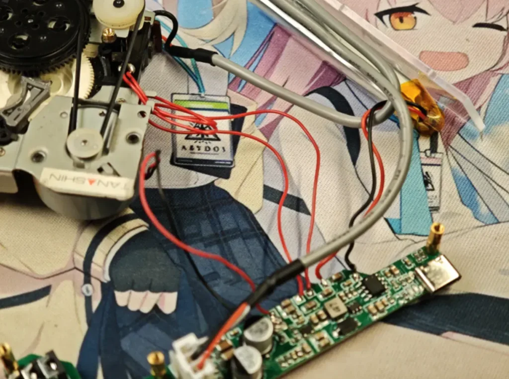
The two spring-contact switches on the mechanism connect to the two corresponding switch terminals on the mainboard; polarity does not matter.
Connect the battery to the “+” and “-” terminals marked on the mainboard.
Motor wiring varies by mechanism model; for the specific mechanism used here, the red wire connects to the motor’s negative (-) terminal, and the black wire connects to the motor’s positive (+) terminal.
If the motor is wired incorrectly, playback will be reversed.
Magnetic Head Shielding Wire
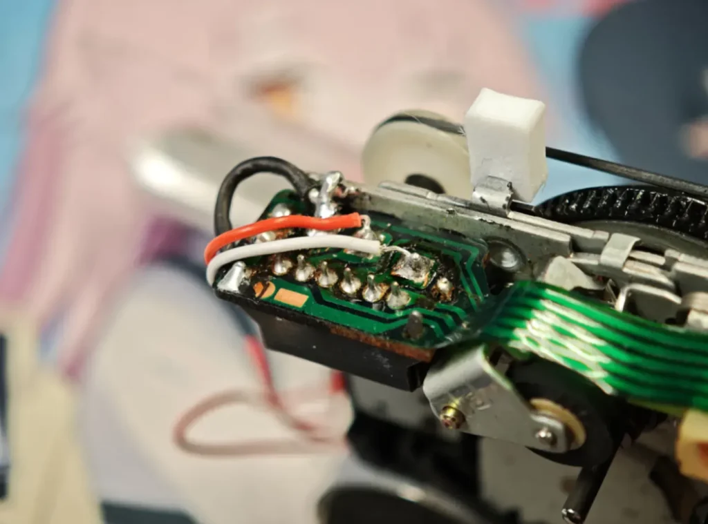
The wiring for the magnetic head shielding cable is shown above.
Connect the white wire to the front solder point, and the red wire to the middle solder point.
Connect the black ground wire to the third solder point. Additionally, use a blade to scrape away the surface coating on the metal chassis of the mechanism, and connect this metal chassis to the black wire. Failure to do so will result in background noise.
Mainboard Shielding Cable
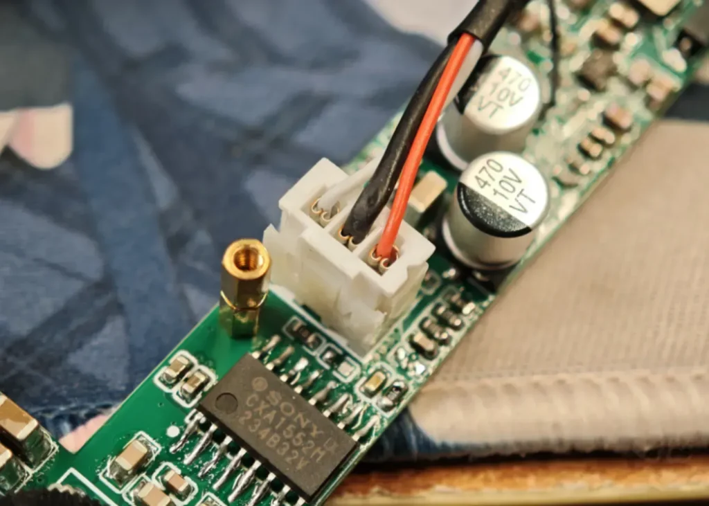
Connect the magnetic head’s shielded cable to the motherboard, paying attention to the wire sequence as shown above.
7.Understanding Key Tape Parameters #
Tape playback quality is closely related to three key parameters: tape speed, wow and flutter, and azimuth.
6.1.Tape Speed #
- Definition: The speed at which magnetic tape moves past the tape head, measured in centimeters per second (cm/s) or inches per second (ips).
- Common Standards:
- Cassette Tapes: 4.76 cm/s
- Reel-to-Reel Tapes: 9.5 cm/s, 19 cm/s, 38 cm/s (Professional Grade)
- Impact:
- Pitch and Duration: Deviations in tape speed result in a shift in pitch—rising if the speed is too fast, or lowering if it is too slow—while simultaneously altering the playback duration.
- High-Frequency Response: Higher tape speeds (e.g., 19 cm/s) enable the recording of a wider frequency range, specifically enhancing high-frequency detail.
- Calibration Methods:
Using a standard test tape (containing fixed-frequency signals), adjust the motor speed or servo system to synchronize the playback frequency with the test signal.
6.2. Wow & Flutter #
- Definitions:
- Wow:Low-frequency speed fluctuation (0.1–10 Hz), manifesting as periodic pitch variations (e.g., “wavy” pitch shifts).
- Flutter:High-frequency speed fluctuation (10–200 Hz), resulting in trembling or distorted sound (e.g., a “quivering” vocal quality).
- Wow: Low-frequency speed fluctuation (0.1–10 Hz), manifesting as periodic pitch variations (e.g., “wavy” pitch shifts).
- Flutter: High-frequency speed fluctuation (10–200 Hz), resulting in trembling or distorted sound (e.g., a “quivering” vocal quality).
- Causes:
Mechanical component defects: motor instability, aging pinch rollers, uneven tape tension, worn bearings, etc.
- Measurement and Standards:
A wow-and-flutter meter is used to measure the percentage (%); the lower the value, the better. High-end cassette decks typically require a reading of less than 0.05%.
- Improvement Measures:
- Regular Maintenance: Clean the magnetic heads and replace aging rubber components (pinch rollers, belts).
- Utilize a high-quality motor and a speed stabilization system (such as quartz-locked phase-locked loop control).
6.3. Azimuth #
- Definition: The angle between the magnetic head gap and the direction of tape travel. Ideally, this angle should be 90° (perfectly perpendicular).
- Impact of Deviation:
- High-Frequency Attenuation: Azimuth mismatch leads to a loss of high-frequency signals (the read/write head is unable to accurately read the magnetic tracks).
- Channel Imbalance: An azimuth error in the stereo head results in a phase difference between the left and right channels, leading to vague soundstage localization.
- Calibration Method:
Using an azimuth test tape (containing high-frequency signals, such as those above 10 kHz), observe the phase of the left and right channel waveforms on an oscilloscope, and adjust the head screws until the waveforms coincide.
Professional equipment may be equipped with an automatic azimuth calibration function.
Summarize #
- Tape speed is the “heartbeat” of a tape system, determining the fundamental pitch and frequency response;
- Wow and flutter reflect the “health” of the mechanical system, influencing sound stability;
- Azimuth is the “angle of dialogue” between the tape head and the tape, determining high-frequency precision and stereo imaging.
8.Tape Parameter Tuning #
8.1.Belt Speed #
Adjusting the belt speed is quite simple.
Just adjust this potentiometer. The acrylic sheet also has corresponding holes for easy adjustment after installation.
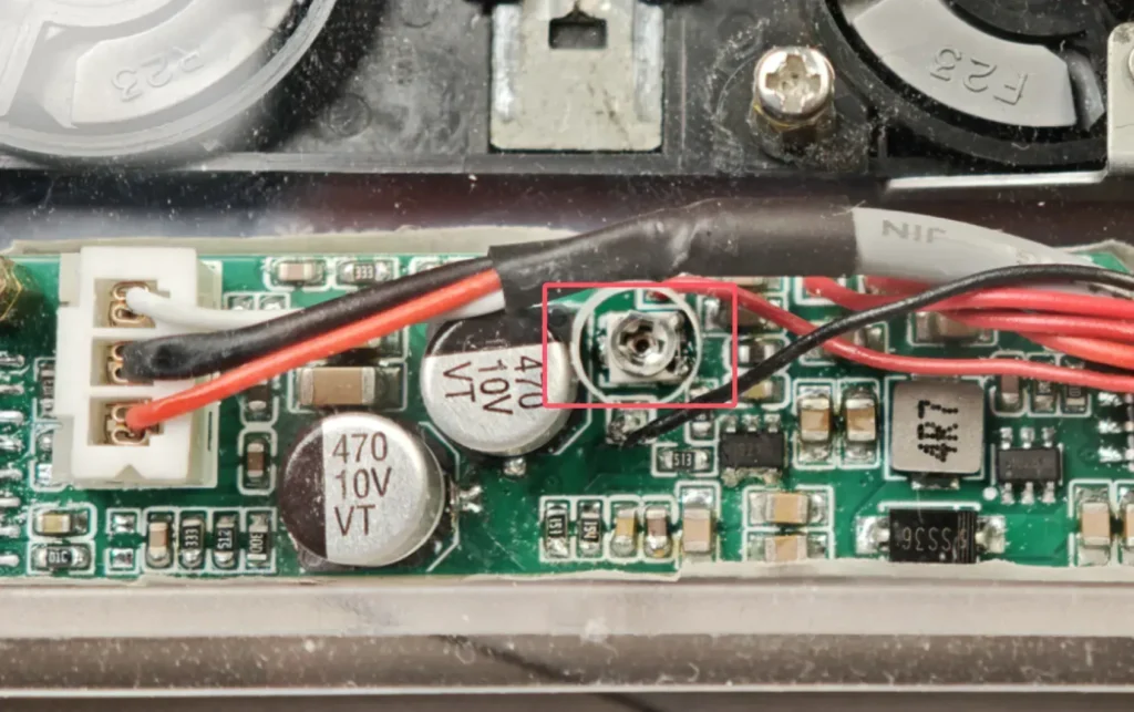
Generally speaking, the proper procedure involves playing a standard test tape and then observing an oscilloscope to verify that the waveforms correspond to the correct signal frequency.
However, standard test tapes are now quite difficult to acquire—and are often rather expensive. Therefore, a practical alternative is to simply purchase a cassette of music you are familiar with; you can then adjust the playback speed until it sounds natural and “right” to your ears—neither too fast nor too slow.
8.2.Shake pendulum instrument #
In the past, wow and flutter measurements were typically performed by playing a standard test tape and observing the results on a dedicated wow and flutter meter.
However, software-based wow and flutter meters are now available, allowing these measurements to be monitored directly on a computer.
The following procedures should be carried out in situations where neither a standard test tape nor a dedicated wow and flutter meter is available.
Since the mechanisms we acquire are typically salvaged units—and even brand-new mechanisms, if stored for extended periods—the drive belts and gears have inevitably undergone significant aging.
Replacing the belt is the most direct and effective solution; that is why I included a belt when purchasing the materials.
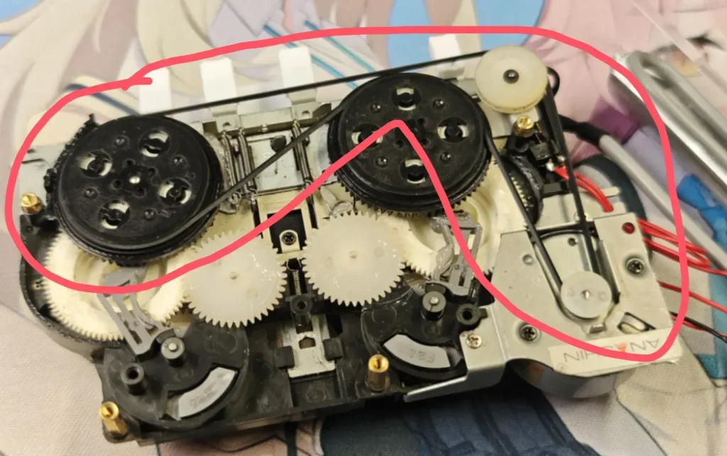
Gear Spot Lubrication Oil
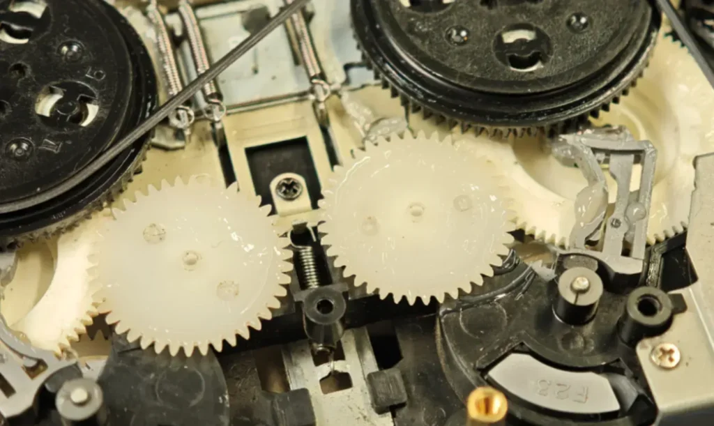
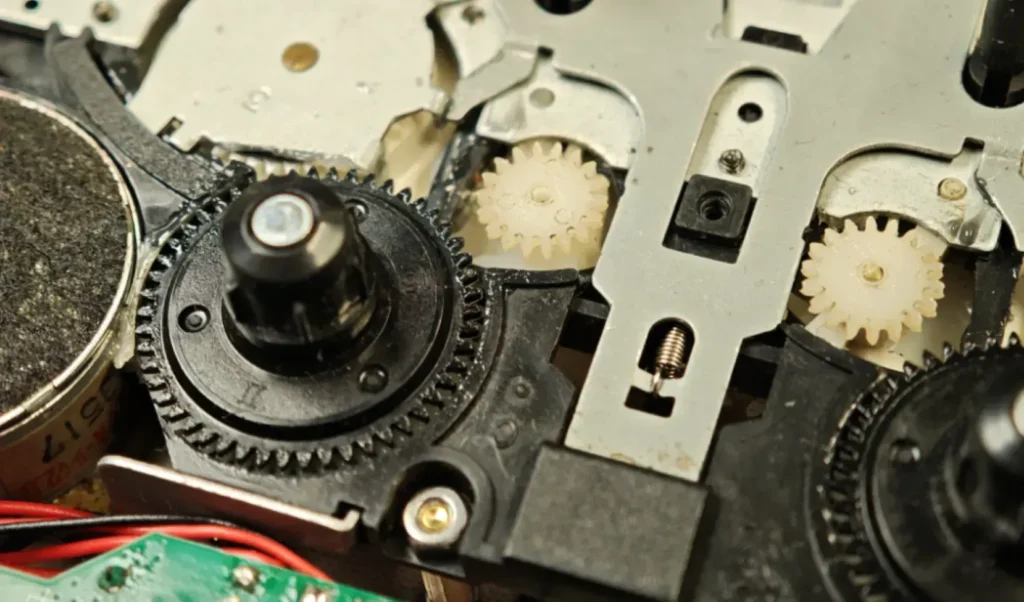
Lubricating oil can be applied to all mechanical rotating parts.
- Check if the pulleys are stable.
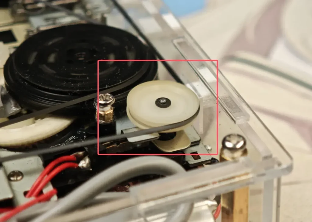
In some disassembled movements, prolonged operation may cause the pulley to exhibit a continuous fluttering motion; this can be resolved by pressing down on the central shaft to stabilize it.
8.3.Azimuth #
Adjusting a tape deck’s azimuth involves aligning the angle of the magnetic head relative to the tape. Typically, this is accomplished by using a standard test tape in conjunction with an oscilloscope.
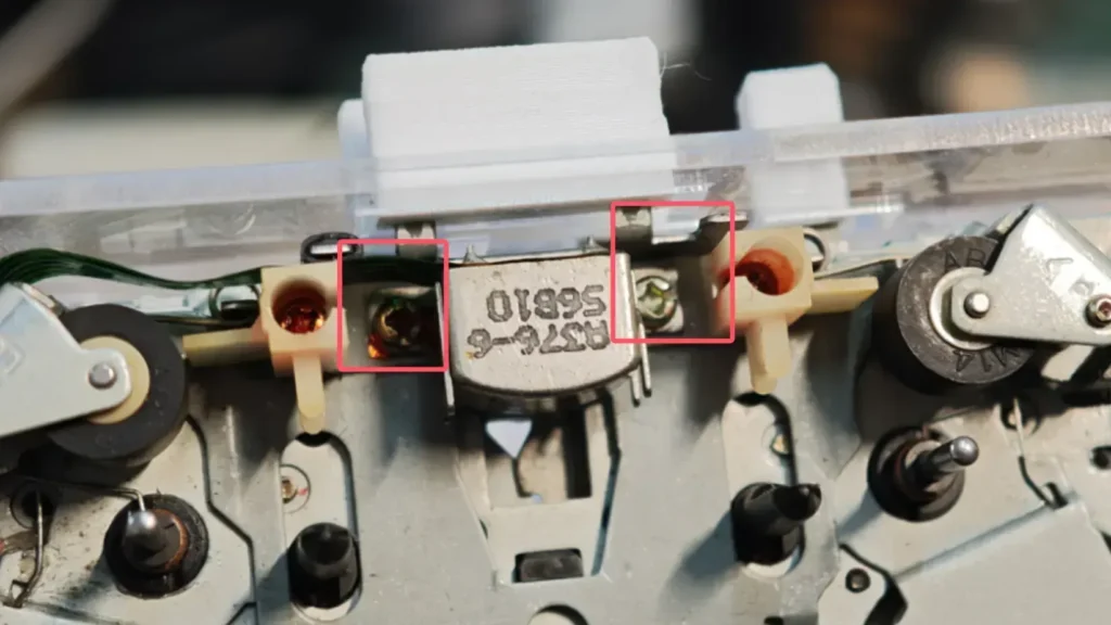
Adjusting the azimuth specifically entails adjusting the screws located on either side of the magnetic head.
If you have purchased a tape deck that has been salvaged from a larger unit, it is usually already properly calibrated and requires no further adjustment.
In the absence of a test tape or specialized equipment, you can tighten the left-side screw as firmly as possible, and then proceed to adjust the right-side screw.
While playing a piece of music with which you are familiar, simply adjust the setting until the gain levels of the left and right audio channels sound approximately equal.
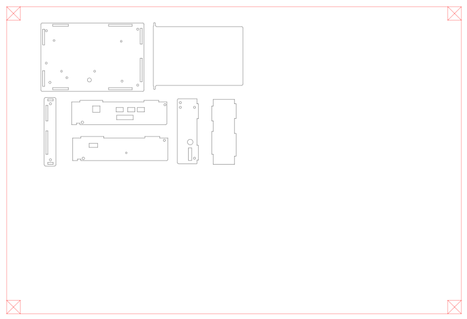
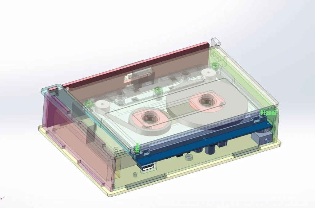
9.Casing and 3D #
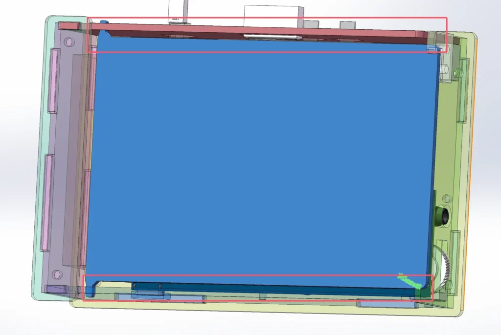
Drawn using SW
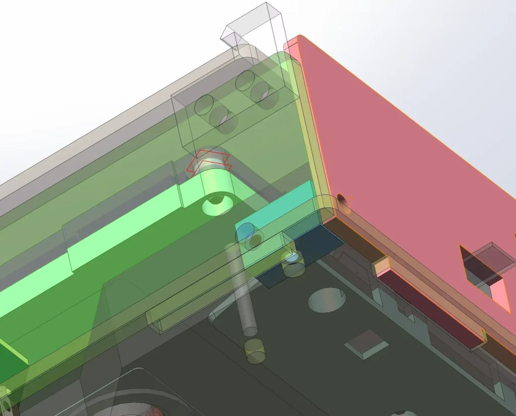
Acrylic Connector
3D Buttons
It should be noted that the dimensions and positioning of the movement’s buttons do not match the technical drawings.

Motherboard
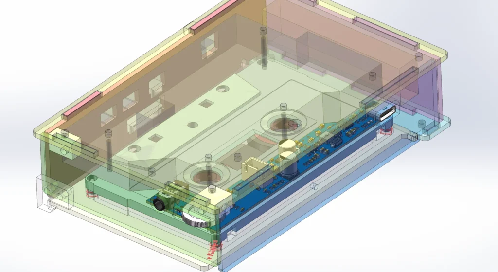
There is a significant amount of play in the top cover; you might want to try adding a bit more material to fill the gap here.
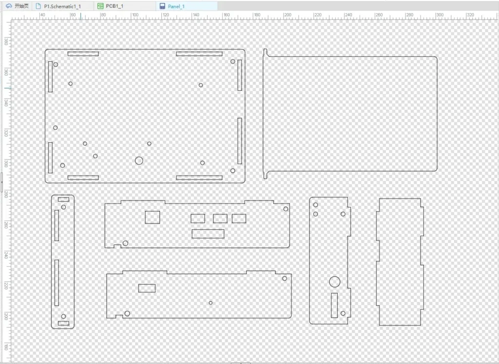
Export DXF for Panel Drawing in LCSC
10.Assembly #
- First, connect the wiring according to the steps outlined in Chapter 6 of the project guide.
- Then, mount the buttons onto the mechanism assembly.
- Assemble the acrylic components as shown in the figure below.
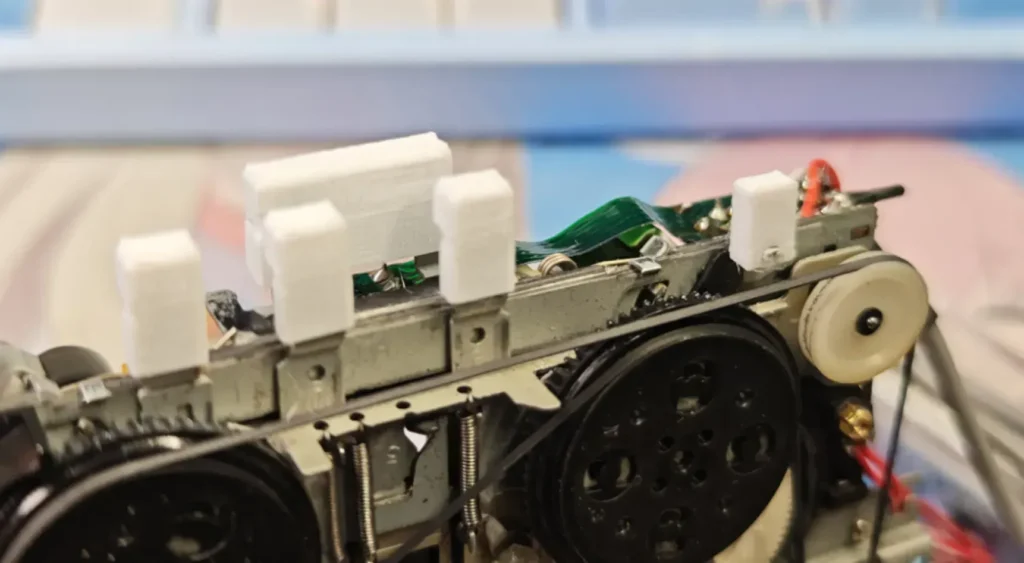
Install M2.3×5 self-tapping screws into the connector.
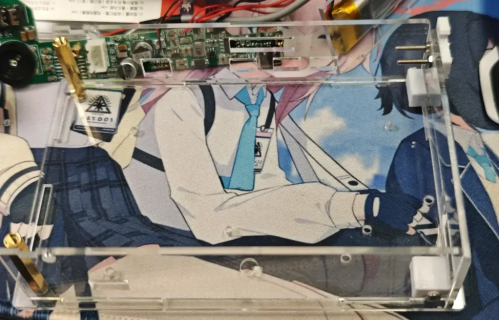
Install the two M2.5 × 27 brass standoffs on the left side, and fasten them with M2.5 × 6 screws.
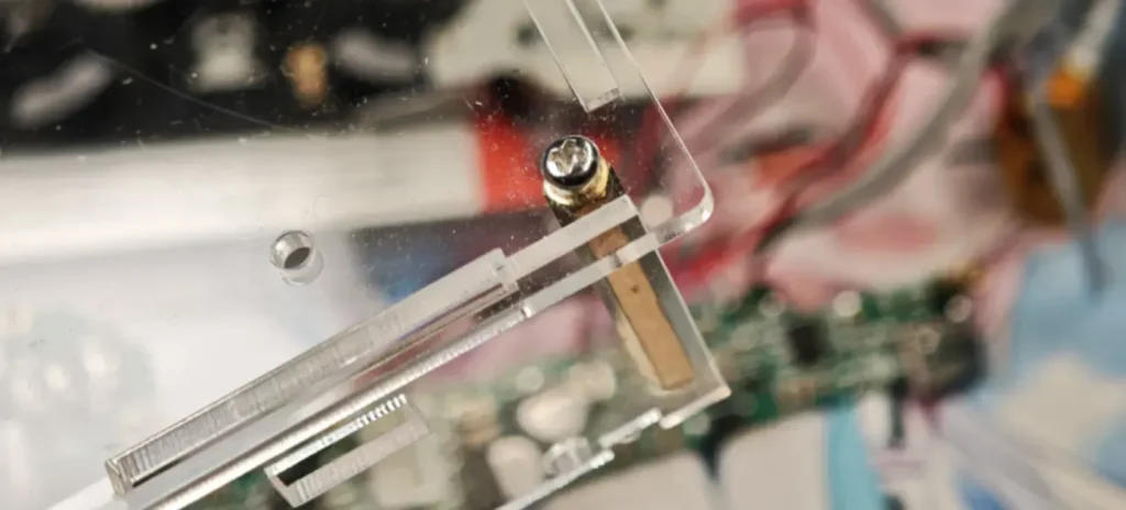
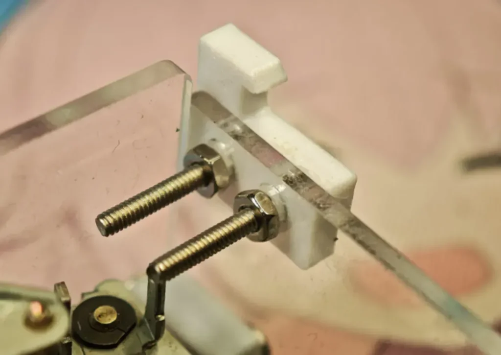
The cover is secured by clips; these can be installed now, or after the mainboard and mechanism have been inserted.
M2×16 screws and M2 nuts are used.
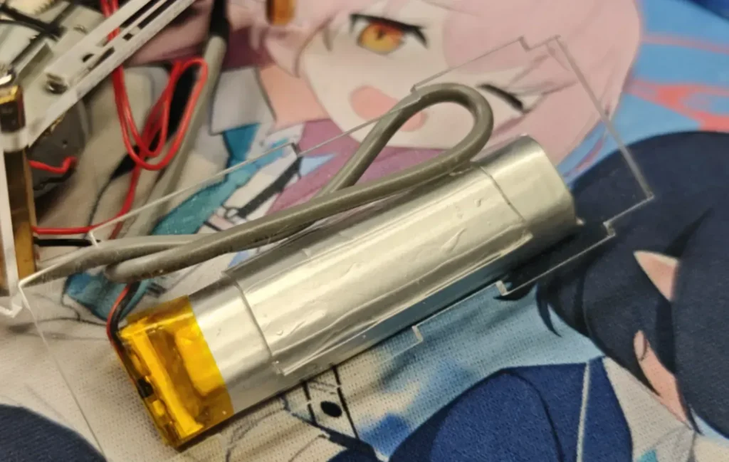
Attach the battery.
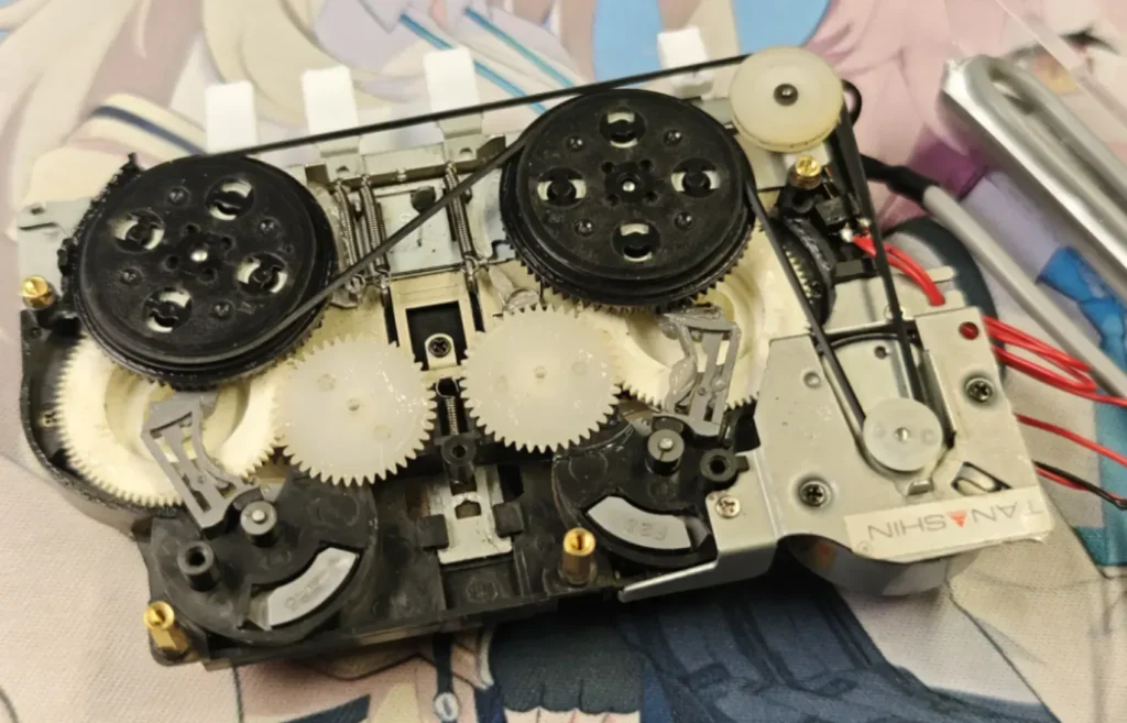
Install the copper standoffs onto the movement: two M2×(2+3) standoffs at the top, and two M2×(7+3) standoffs at the bottom; simultaneously, secure the reverse side with M2 nuts.
Install the M2*8+3 standoffs onto the motherboard, and secure them with M2 nuts on the back.
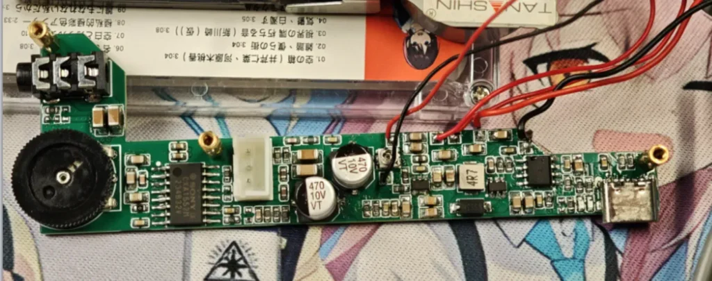
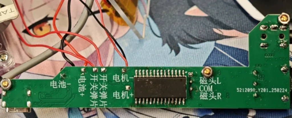
Acrylic on the Motherboard
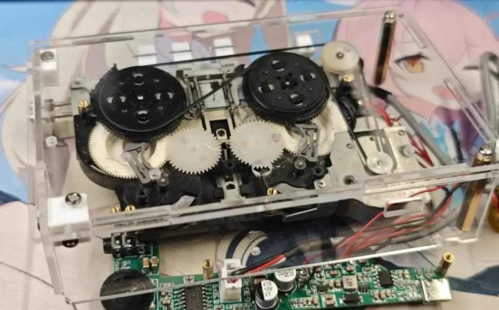
And secure it using M2*6 screws.
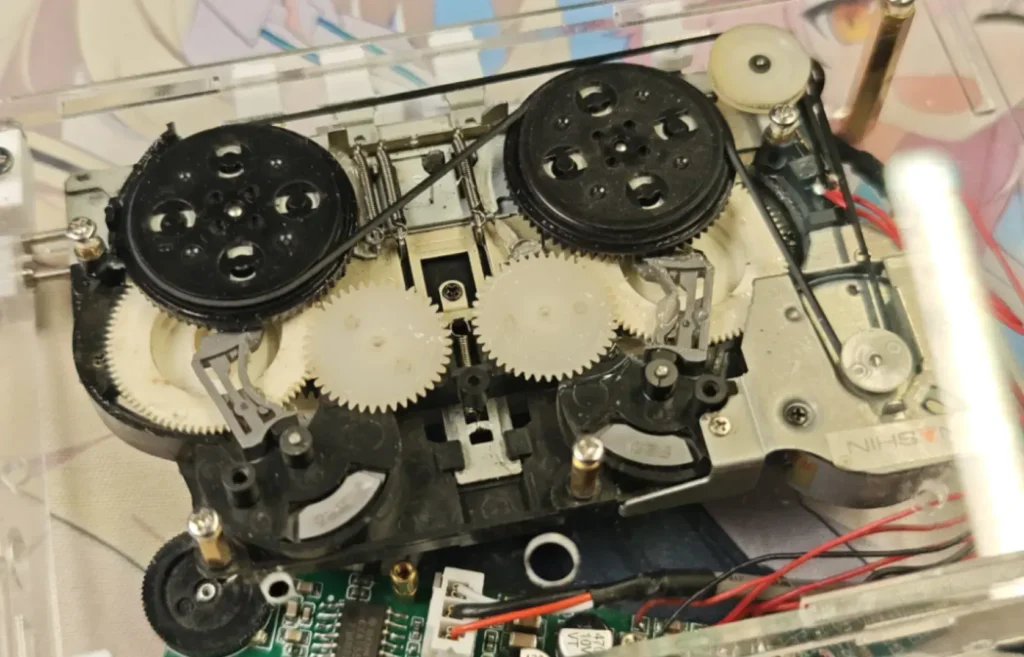
Mount the acrylic panel onto the motherboard and secure it with M2*6 screws, then manage the cables.
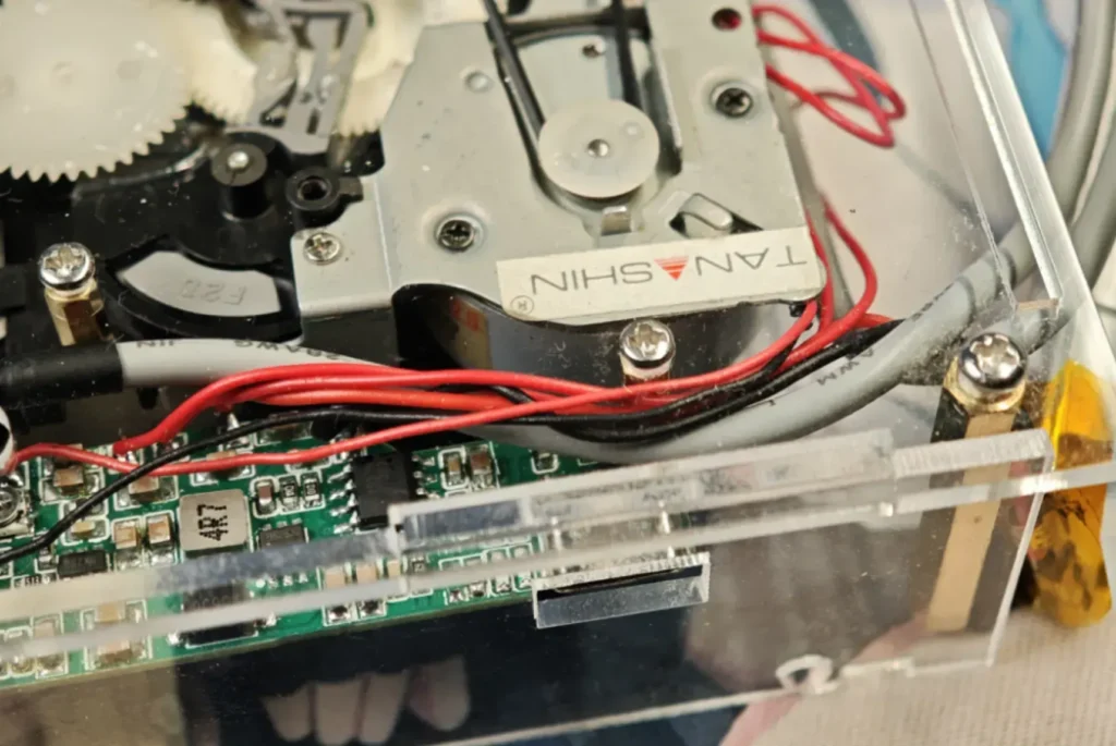
Assemble the battery side cover with the top cover, and secure the other end of the M2.5×27 copper standoff using an M2.5×6 screw.
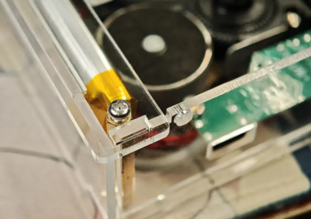
Install the Top Cover
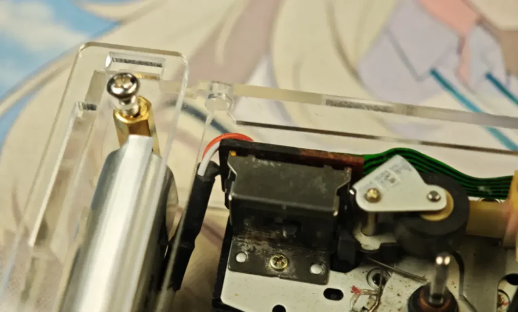
Check whether the latches securely fasten the top cover.
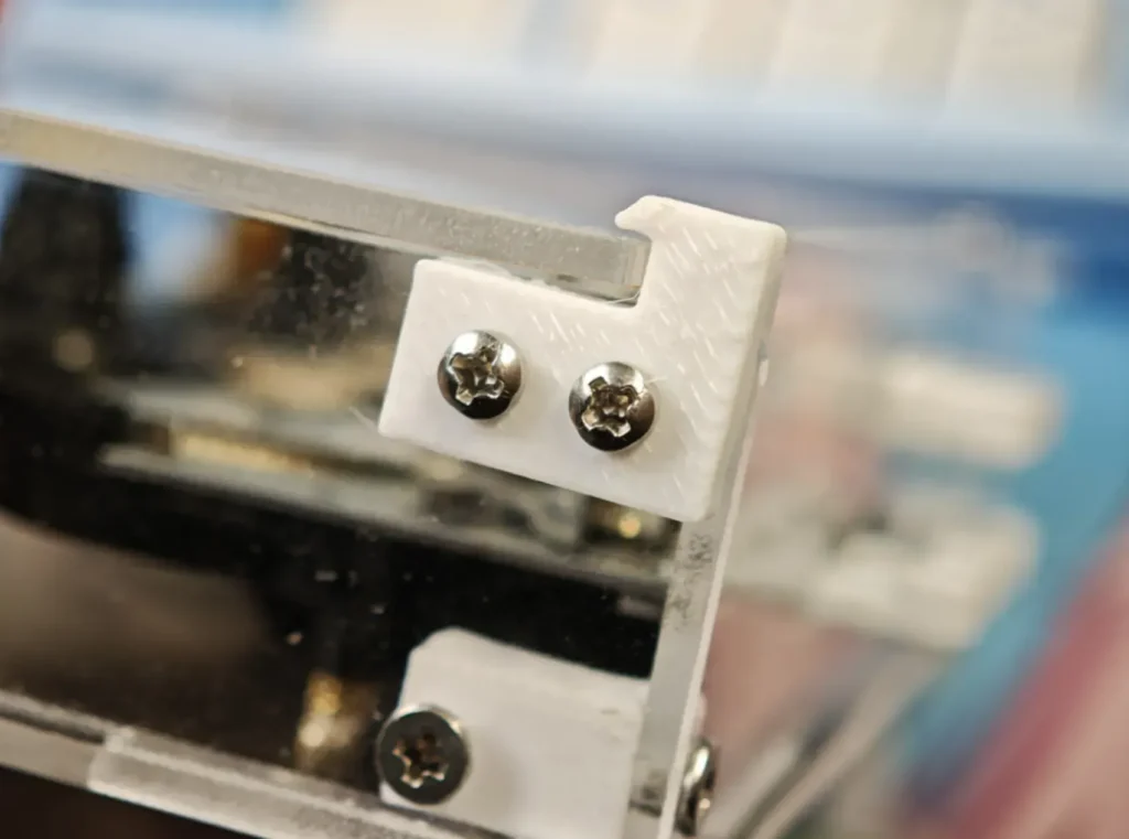
- Cotton padding is affixed beneath the top cover to press against the cassette tape.
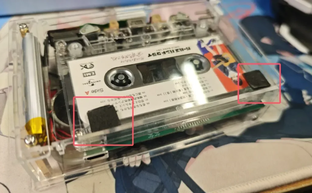
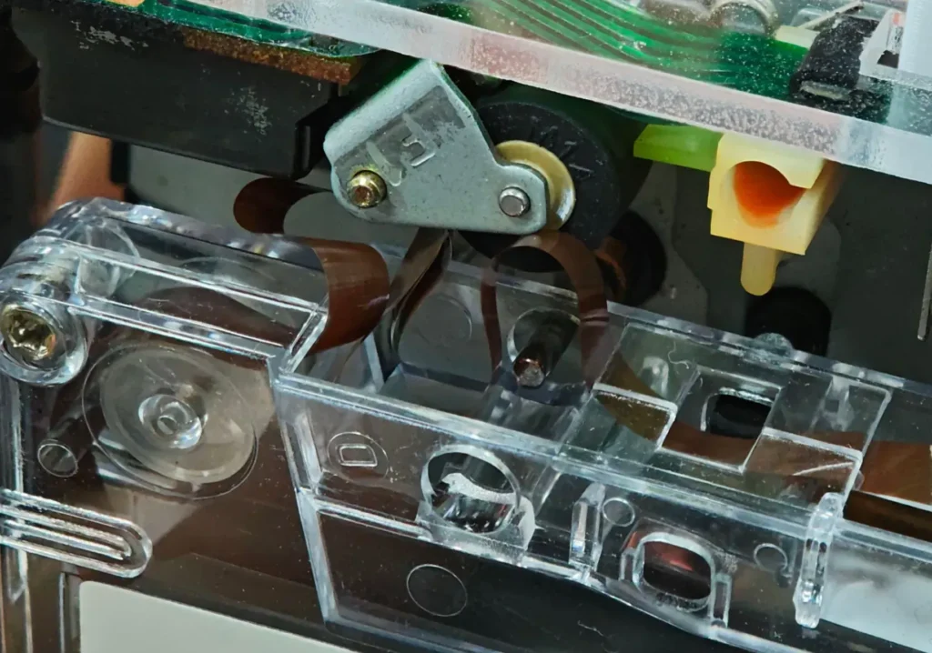
If the cotton pad is not inserted to press against the tape, the lower take-up spindle will disengage from the tape reel spindle; this results in tape bunching behind the playback pinch roller, causing damage to the tape.
11.Summary #
Looking back at the history of music media, this project offers a hands-on experience with the cassette tape technology of the last century.
This project involves recreating a device with low overall production costs—specifically, the cost per individual unit is minimal—resulting in a finished product that is portable, personal, and aesthetically pleasing.
It is an ideal entry-point for beginners looking to learn the ropes of DIY audio reproduction.
We also welcome cassette tape enthusiasts and experts to offer critiques on the project, or to engage in discussions regarding potential improvements and corrections.
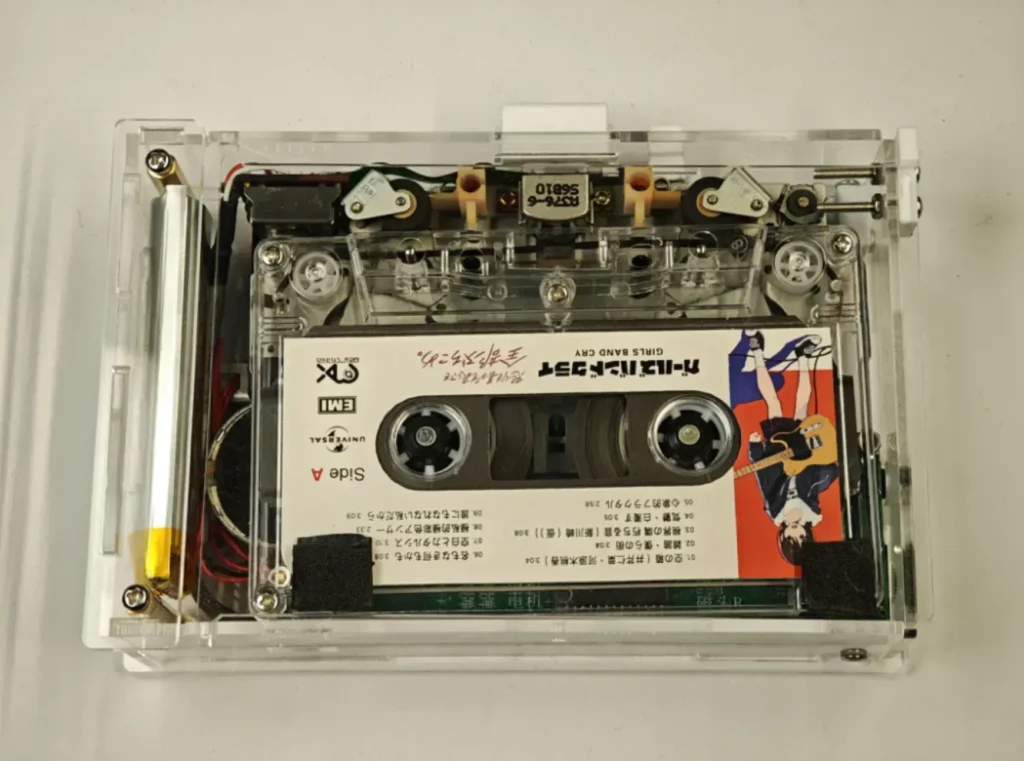
Note: Given the vintage nature of cassette tape technology, it is normal to hear a “clicking” or static-like noise during playback today. This interference is caused by wireless signals from mobile phones and 2.4 GHz devices. Since the era in which this technology was developed predated the widespread proliferation of wireless internet terminals and 2.4 GHz devices, the technology of that time was not designed to account for such interference issues.
Optimization Suggestion: Add a shielding cover to the head amplifier chip.
Design Drawings