
The DYP-L02 Ultrasonic Liquid Level Sensor is designed for non-contact liquid level measurement and upper/lower level detection in sealed containers.
Unlike conventional wetted liquid sensors, the L02 can operate from outside the container without drilling holes or placing a sensing element directly into the liquid.
When mounted underneath a container, it can measure liquid level height. When mounted on the outside wall of a container, it can detect whether liquid is present at a specific monitoring point.
This makes the sensor suitable for applications where direct contact with the liquid is undesirable or where the container needs to remain sealed.
Key Features #
The DYP-L02 provides:
- Non-contact liquid level measurement
- 2.8–5 V operating voltage
- 20–2000 mm liquid level measurement range
- 1 mm resolution
- Real-time tracking across the measurement range
- Multiple output configurations
- Adaptive blind-zone detection
- Operating temperature from -15°C to +60°C
- Storage temperature from -25°C to +80°C
- ESD protection compliant with IEC 61000-4-2
- Compact sensor design
- Automatic and triggered operating modes
The sensor uses an intelligent algorithm to identify container characteristics and automatically adapt its blind zone.
Typical Applications #
The L02 can be used for liquid detection through containers made from dense materials including:
- Steel
- Iron
- Glass
- Ceramic
- Non-foamed plastics
It is intended for clean, single-component liquids or miscible liquid mixtures without substantial sediment.
Typical applications include:
- Smart drinking cups
- Smart beer kegs
- Smart liquefied-gas systems
- Intelligent liquid-control equipment
- Sealed-container liquid monitoring
For reliable measurement, the container should have a reasonably regular shape and a relatively flat mounting surface.
Technical Specifications #
| Parameter | L023MUW | L023MTW | L023MGDW | L023MPNW |
|---|---|---|---|---|
| Operating Voltage | 2.8–5 V | 2.8–5 V | 2.8–5 V | 2.8–5 V |
| Standby Current | 1 µA | 1 µA | 1 µA | 1–8000 µA |
| Average Current | 2.5–5 mA | 2.5–5 mA | 2.5–5 mA | 2.5–15 mA |
| Blind Zone | Adaptive | Adaptive | Adaptive | Adaptive |
| Liquid Level Range | 20–2000 mm | 20–2000 mm | 20–2000 mm | 20–2000 mm |
| Operating Cycle | 1 s | Triggered | 1 s | 1 s |
| Output | Automatic UART | Triggered UART | TTL Switching | PNP/NPN Switching |
| Resolution | 1 mm | 1 mm | 1 mm | 1 mm |
| Response Time | 1 s | 1 s | 1 s | 1 s |
| Repeatability Error | ±1 mm | ±1 mm | — | — |
| Measurement Angle | 3–12° | 3–12° | 3–12° | 3–12° |
For the UART models, room-temperature accuracy is specified as:
±(5 + S × 0.5%) mm
where S represents the current liquid level height.
Actual blind zone and measurement performance depend on the container material and wall thickness.
Mechanical Dimensions #
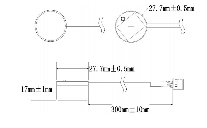
According to the mechanical drawing in the specification:
- Sensor diameter: 27.7 ± 0.5 mm
- Sensor height: 17 ± 1 mm
- Cable length: 300 ± 10 mm
The sensor’s compact form factor allows it to be mounted externally on suitable containers.
Pin / Lead Definitions #
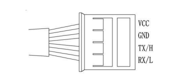
The L02 uses four electrical connections:
| Pin | Lead | Description |
|---|---|---|
| 1 | VCC | 2.8–5 V power input |
| 2 | GND | Power ground |
| 3 | TX/H | UART output / active-high TTL output / PNP output |
| 4 | RX/L | UART input / active-low TTL output / NPN output |
The function of TX/H and RX/L depends on the selected sensor model and output configuration.
Environmental Conditions #
| Parameter | Minimum | Typical | Maximum |
|---|---|---|---|
| Storage Temperature | -25°C | 25°C | 80°C |
| Storage Humidity | — | 65% RH | 90% RH |
| Operating Temperature | -15°C | 25°C | 60°C |
| Operating Humidity | — | 65% RH | 80% RH |
Humidity specifications are non-condensing and vary according to ambient temperature.
Electrical Conditions #
| Parameter | Minimum | Typical | Maximum |
|---|---|---|---|
| Input Voltage | 2.8 V | 5 V | 5.25 V |
| Peak Current | — | — | 130 mA |
| Input Ripple | — | — | 50 mV p-p |
| Input Noise | — | — | 100 mV p-p |
| ESD | — | — | ±4 kV / ±8 kV |
The probe housing and output leads comply with IEC 61000-4-2 for the stated ESD specification.
UART Output #
The L02 supports two UART operating modes depending on the selected model.
Automatic UART #
The sensor performs one measurement every second. The TX line automatically outputs the current measured liquid level.
Triggered UART #
A high-level pulse applied to RX initiates measurement on its falling edge. The sensor then outputs one liquid-level reading through TX.
The interval between triggers must be greater than 1 second.
UART Communication Settings #
| Setting | Value |
|---|---|
| Signal Level | TTL |
| Data Bits | 8 |
| Stop Bits | 1 |
| Parity | None |
| Baud Rate | 9600 bps |
UART Data Format #
Each reading consists of four bytes:
| Field | Description | Length |
|---|---|---|
| Header | Fixed value 0xFF | 1 byte |
| Data_H | Upper 8 bits of distance data | 1 byte |
| Data_L | Lower 8 bits of distance data | 1 byte |
| SUM | Checksum | 1 byte |
The checksum is calculated as:
SUM = (Header + Data_H + Data_L) & 0x00FFExample:
Header = 0xFF
Data_H = 0x07
Data_L = 0xA1
SUM    = 0xA7
Liquid level:
Liquid Level = Data_H × 256 + Data_L
             = 0x07A1
             = 1953 mm
Therefore, this example represents a measured liquid level of 1953 mm.
TTL Switching Output #
Active-High Output #
When liquid is detected:
- LED flashes once per second.
- TX output is at VCC.
When no liquid is detected:
- LED remains continuously on.
- TX output is 0 V.
The TTL output provides a logic-level signal only and cannot directly drive a load.
Active-Low Output #
When liquid is detected:
- LED flashes once per second.
- RX output is 0 V.
When no liquid is detected:
- LED remains continuously on.
- RX output is at VCC.
This output is also intended only as a high/low logic signal and cannot directly drive a load.
PNP / NPN Switching Output #
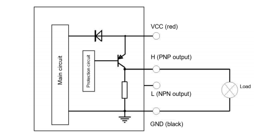
PNP Output #
When liquid is detected, the internal transistor switches on and output H rises to VCC.
When no liquid is detected, the transistor switches off and output H is 0 V.
Use a resistive load drawing less than 100 mA.
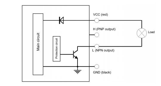
NPN Output #
When liquid is detected, the internal transistor switches on and output L connects directly to GND.
When no liquid is detected, the transistor switches off and output L becomes an open circuit.
The resistive load must draw less than 100 mA.
LED Status Indicators #
The sensor’s LED provides a quick indication of its operating state:
| LED Status | Meaning |
|---|---|
| Continuously On | Sensor powered; no liquid detected |
| Slow Flashing | Liquid detected; flashes once per second |
| Triggered UART | Flashes once for every triggered measurement |
In triggered UART mode, the LED remains off when no measurement is being triggered.
Choosing the Correct DYP-L02 Model #
There are four L02 variants. The output configuration is determined at the factory; one sensor does not simultaneously support multiple output configurations.
| Model | Output / Function |
|---|---|
| DYP-L023MUW-V1.0 | Automatic UART output |
| DYP-L023MTW-V1.0 | Triggered UART output; 1 µA standby current |
| DYP-L023MGDW-V1.0 | TTL high/low logic output; cannot drive a load |
| DYP-L023MPNW-V1.0 | PNP/NPN output; load capability up to 100 mA |
Which model should I use #
For applications requiring continuous numerical liquid-level data, choose the automatic UART model.
For low-power systems where measurements are initiated only when required, use the triggered UART model.
For simple liquid-present/liquid-absent detection connected to a microcontroller, the TTL version provides a logic-level output.
For applications requiring a switching output capable of driving a resistive load up to 100 mA, use the PNP/NPN version.
Reliability Testing #
The L02 specification includes environmental, vibration and drop testing, including:
- 60°C / 85% RH powered operation for 72 hours
- -15°C powered operation for 72 hours
- 80°C / 80% RH storage for 72 hours
- -25°C storage for 72 hours
- 10–200 Hz vibration testing
- 1.2 m free-fall testing
After testing, the sensor must remain functional with performance degradation of no more than 10%.
Important Installation and Usage Notes #
Sensor performance depends on the actual container and installation conditions.
Keep the following points in mind:
- Blind zone and maximum detectable liquid level vary with container material.
- Container wall thickness also affects the blind zone and maximum detectable level.
- Measurements can become unstable when the liquid level is outside the effective measurement range.
- Significant movement or tilting of the liquid surface can affect readings.
- Electromagnetic compatibility should be considered during system design.
- Applications operating close to the sensor’s limiting parameters should be evaluated carefully before final system integration.
Packaging #
Standard packaging is supplied by default.
Packaging materials may also be customized according to incoming quality control (IQC) requirements.


